
Apparatus for measuring imaging spectrograph

an imaging spectrograph and apparatus technology, applied in the direction of optical radiation measurement, instruments, spectrometry/spectrophotometry/monochromators, etc., can solve the problems of only obtaining spectral information, unable to acquire spectral information, and the optical image technique can only measure the spatial information of an object, so as to increase both spectral resolution and spatial resolution

Active Publication Date: 2006-04-13
IND TECH RES INST
View PDF20 Cites 32 Cited by
  • Summary
  • Abstract
  • Description
  • Claims
  • Application Information

AI Technical Summary

Benefits of technology

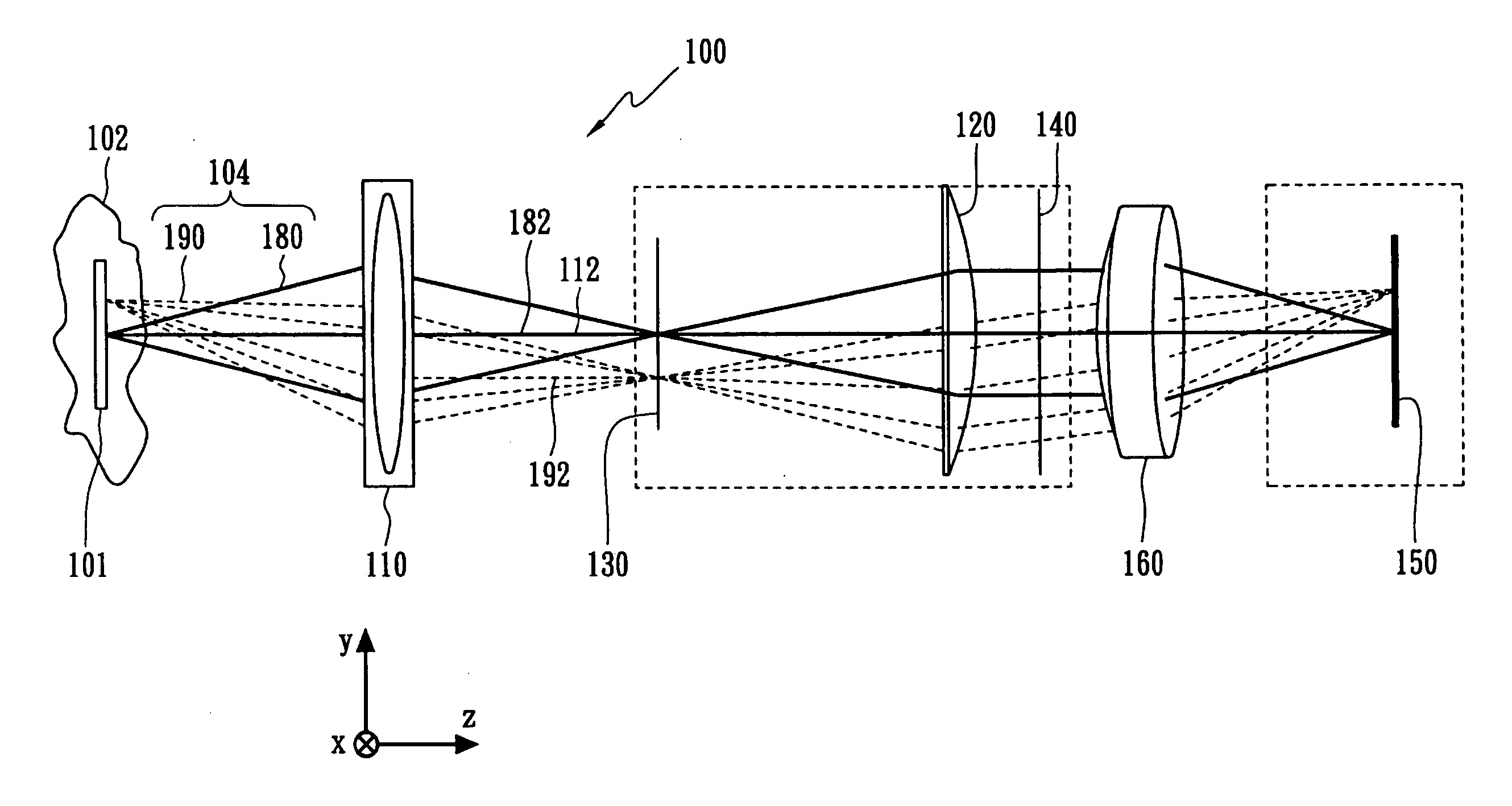
[0011] Regardless of on-axis or off-axis, the optical energy in the field of view of the object can propagate into the dispersing device in a substantially collimated manner since the apparatus possesses the imaging side telecentric lens and the aspheric collimating mirror. In addition, the apparatus uses the achromatic lens to reduce the position difference caused by the aberration, and rays with different wavelengths in the field of view of the object can form a very small imaging spot on the optical sensor regardless of on-axis or off-axis. As a result, the optical energy with different wavelengths from the object can form imaging spots substantially without diffusion effect on the optical sensor. Consequently, the present invention can increase both the spectral resolution and the spatial resolution simultaneously, and therefore can be used to measure imaging spectrograph with high-density channel.

Problems solved by technology

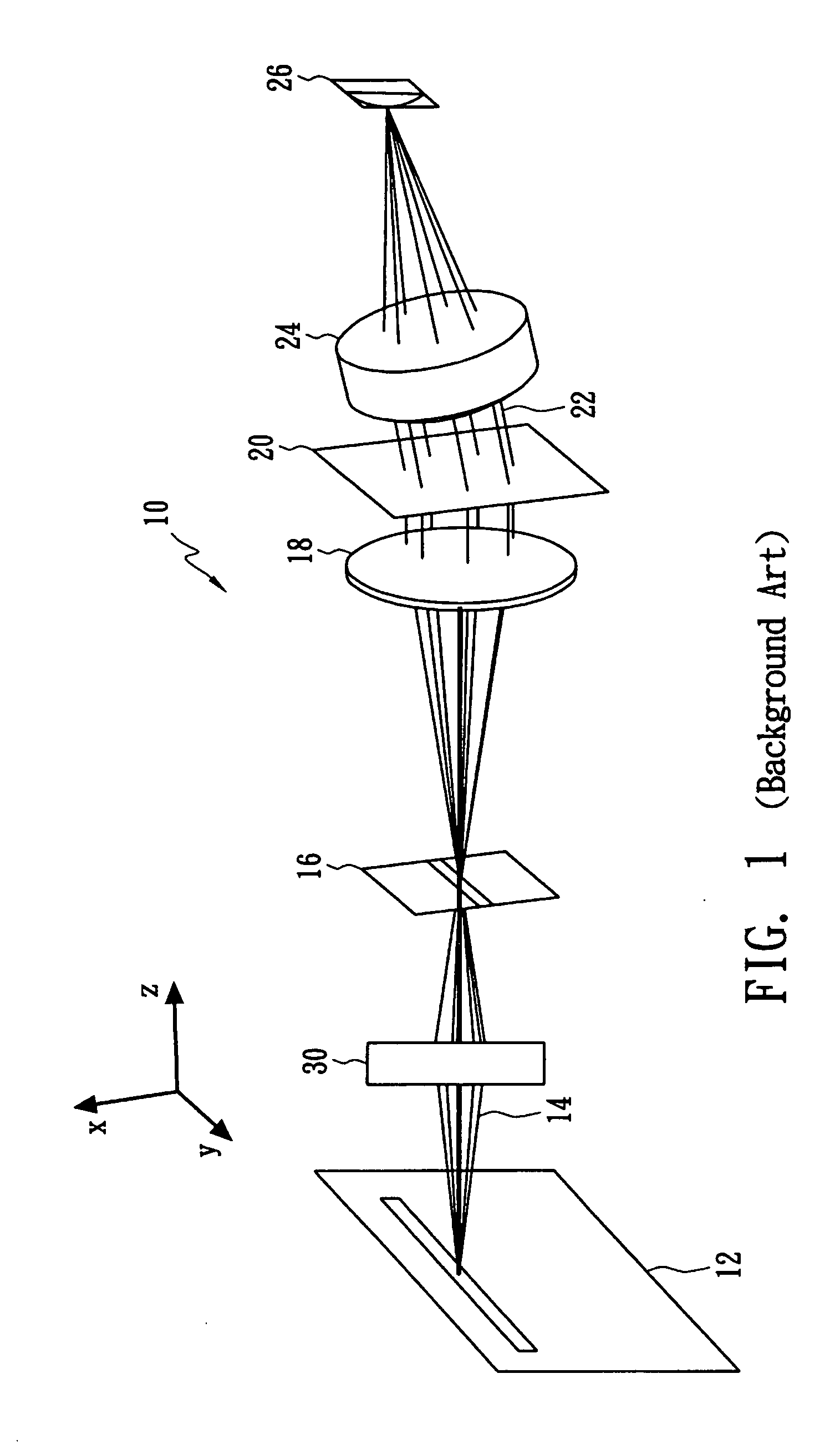
Generally speaking, an optical image technique can only measure spatial information of an object, i.e., the image of the object, but cannot acquire spectral information.
In other words, the spectral information can only be obtained when an additional light-splitting device is incorporated into an optical imaging system.
The point scanning take a relatively long measuring time for moving the probe or the object in two-dimensional manner and the measured data needs to be combined point by point, so the obtained image tends to distort.
On the contrary, the wavelength resolution of the global imaging is limited for using light-splitting devices such as the optical filter.
Consequently, the above-mentioned two methods are not suitable for measuring an object with a larger area rapidly and at high spatial / spectral resolution.
Theses aberration results in severe expansion and distortion of imaging light spots on 2D sensor, and adjacent imaging light spots is not distinguishable due to overlapping.
Consequently, neither the spatial nor spectral resolution cannot be improved.
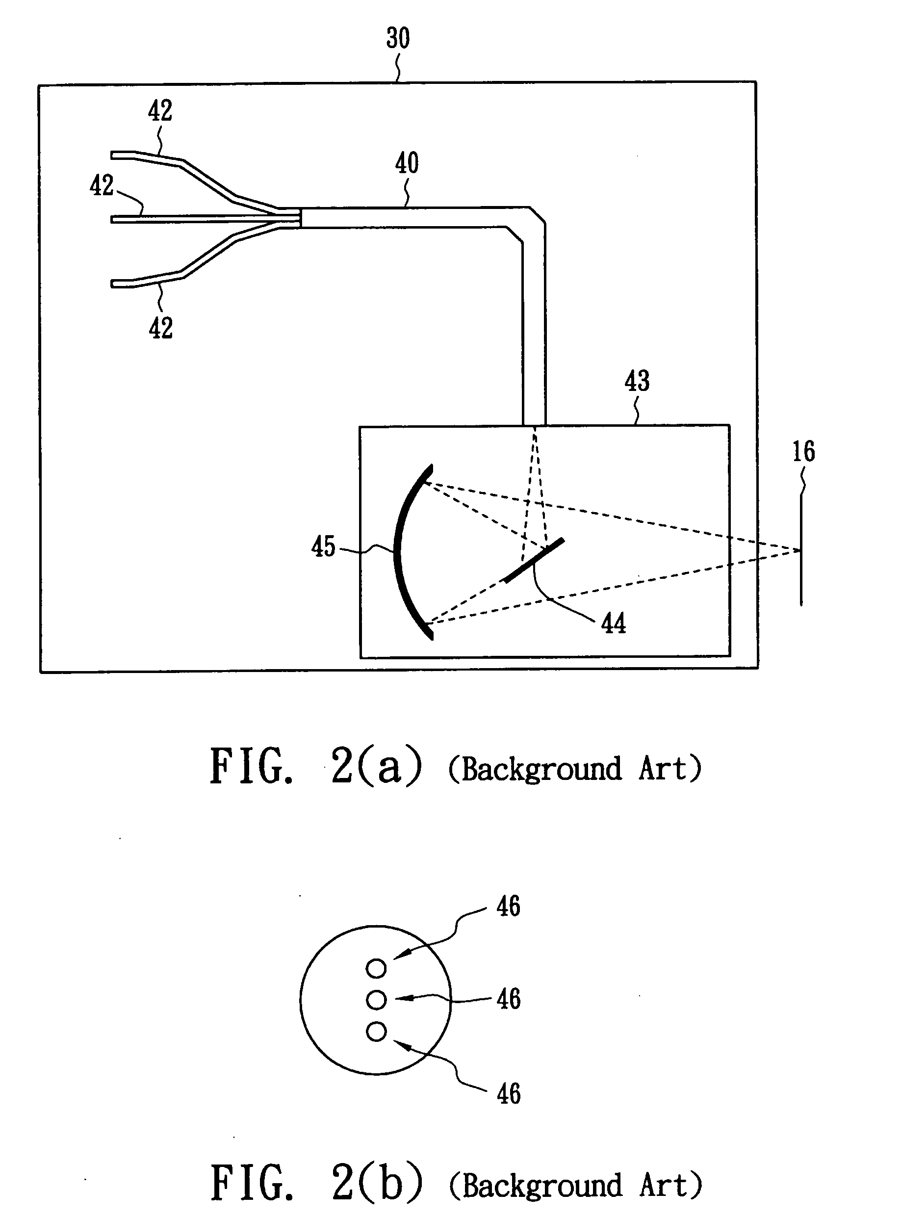
Consequently, available channels are limited, and the channel of the collector 30 in FIG. 2 is only 3.
In addition, the optical energy 14 can be collected from the object 12 only by closing the multi-track fiber 40 to the object 12, which results in difficulty in measuring.
In addition, such a de-collimation will also cause extra aberration, which further reduces the spectral resolution on the CCD 26.
Therefore, the channels available to measure cannot be increased due to the limitation of the spectral / spatial resolution.
Hence, such a design can only be used in the comparison with low resolution, and cannot generate the imaging spectrograph with real high spatial / spectral resolution.

Method used


Image

  • Apparatus for measuring imaging spectrograph
  • Apparatus for measuring imaging spectrograph
  • Apparatus for measuring imaging spectrograph

Examples


first embodiment

[0021]FIG. 4 illustrates an apparatus 100 for measuring imaging spectrograph according to the present invention. The apparatus 100 comprises an imaging side telecentric lens 110 for collecting optical energy 104 from an object 102, an optical slit 130 positioned behind the imaging side telecentric lens 110, an aspheric lens 120 for collimating the light beam from the optical slit 130, a dispersing device 140 for separating the light beam into a plurality of rays with different wavelengths and take-off angles, an achromatic lens 160 for focusing the rays, and an optical sensor 150 for detecting the optical intensity of the rays.

[0022] The dispersing device 140 can be a transmissible diffraction grating, and the optical sensor 150 can be a CCD or 2D array sensor. That is, the optical sensor 150 can consist of several photo-detectors arranged in 2D array. In FIG. 4, X-axis is dispersion axis, and the dispersing device 140 separates the optical energy 104 in the X-axis. The line-shaped ...

second embodiment

[0027]FIG. 8 illustrates an apparatus 200 for measuring imaging spectrograph according to the present invention. Compared to the apparatus 100 in FIG. 4, which uses a transmissible architecture, the apparatus 200 in FIG. 8 uses a reflective architecture. Particularly, the apparatus 200 uses a reflective aspheric lens 220, a reflective diffraction grating 240 and a reflective mirror 260.

[0028] Compared to the prior art, the present invention can increase both the spectral resolution and the spatial resolution simultaneously; therefore, it can be used to measure imaging spectrograph with high-density channel.


PUM


Abstract

The present invention discloses an apparatus for measuring spectrum and image with high spatial resolution and spectral resolution. The apparatus comprises an imaging side telecentric lens for collecting light from an object, an optical slit positioned behind the imaging side telecentric lens, an aspheric lens for collimating lights from the optical slits, a dispersing device for separating the lights of different wavelengths into a plurality of sub-rays of different entrance angle, an achromatic lens for focusing the sub-rays, and an optical sensor for detecting the optical intensity of the sub-rays. The dispersing device can be a transmission or reflection diffraction grating, and the optical sensor may consist of a plurality of photo-detectors positioned in a two dimensional array.

Description

BACKGROUND OF THE INVENTION [0001] (A) Field of the Invention [0002] The present invention relates to an apparatus for measuring imaging spectrograph, and more particularly, to an apparatus for measuring spectrum and image with high spatial resolution and spectral resolution. [0003] (B) Description of the Related Art [0004] Generally speaking, an optical image technique can only measure spatial information of an object, i.e., the image of the object, but cannot acquire spectral information. To acquire both spatial and spectral information, the optical image technique needs extra spectral measuring technique. In other words, the spectral information can only be obtained when an additional light-splitting device is incorporated into an optical imaging system. [0005] Conventional imaging spectrograph measuring technique can be classified as a point scanning and a global imaging. The point scanning take a relatively long measuring time for moving the probe or the object in two-dimension...

Claims


Application Information

Patent Timeline
IPC IPC(8): G01J3/28G01J3/02
CPCG01J3/02G01J3/0208G01J3/2823
Inventor WANG, HAU WEIYANG, FU SHIANG
Owner IND TECH RES INST
Learn More