
A macro shooting method and terminal

A shooting method and macro technology, which can be used in TV, color TV parts, TV system parts and other directions, and can solve the problems of unable to obtain satisfactory macro shooting images, unable to obtain focusing effect, unable to locate specific details, etc.

Active Publication Date: 2019-08-16
NUBIA TECHNOLOGY CO LTD
View PDF5 Cites 0 Cited by
  • Summary
  • Abstract
  • Description
  • Claims
  • Application Information

AI Technical Summary

Problems solved by technology

Users often cannot accurately locate the specific details they want to shoot by manually clicking the target object for macro shooting, especially for shooting a specific part of the target object. The current manual touch focus shooting method cannot Accurate focusing effect is obtained, so users usually cannot obtain satisfactory macro shooting images when using terminal equipment for macro shooting

Method used


Image

  • A macro shooting method and terminal
  • A macro shooting method and terminal
  • A macro shooting method and terminal

Examples


Embodiment 1

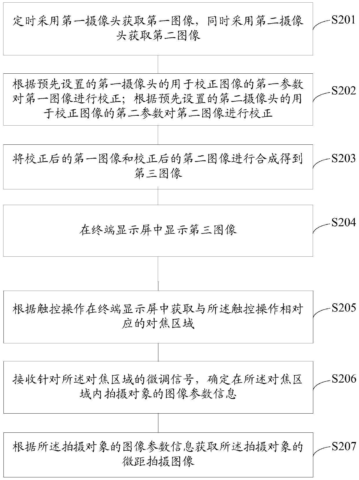
[0098] See figure 2 , Which shows that an embodiment of the present invention provides a macro shooting method, taking the terminal display screen as a touch display screen as an example for description, the method may include:

[0099] S201: The first camera is used to acquire the first image at regular intervals, and the second camera is used to acquire the second image at the same time;

[0100] In this step, the first camera and the second camera form a binocular camera and have a common field of view. It can be a left camera and a right camera on the same horizontal plane, or an upper camera and a lower camera on the same vertical plane. It may be other situations, which is not limited in the embodiment of the present invention.

[0101] S202: Correct the first image according to the preset first parameter of the first camera for correcting the image; correct the second image according to the preset second parameter of the second camera for correcting the image;

[0102] In this...

Embodiment 2

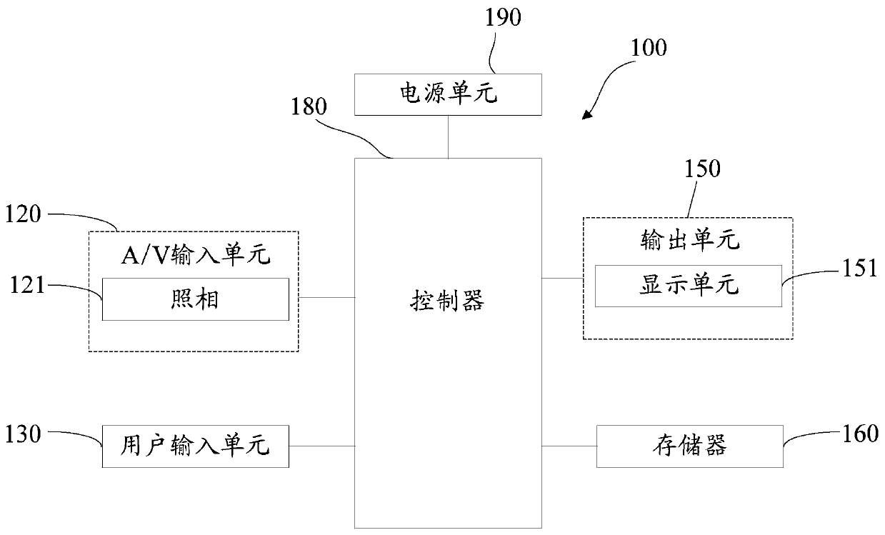
[0226] See Picture 11 , Which shows a schematic structural diagram of a macro shooting terminal 8 provided by an embodiment of the present invention. The terminal 8 may include: a first acquisition module 801, a correction module 802, a synthesis module 803, a display module 804, and a second acquisition module 805, receiving module 806, and determining module 807; among them,

[0227] The first acquisition module 801 is configured to periodically use a first camera to acquire a first image, and at the same time use a second camera to acquire a second image;

[0228] The correction module 802 is configured to correct the first image according to the preset first parameter of the first camera for correcting the image; perform the second image correction according to the preset second parameter of the second camera for correcting the image Correction;

[0229] The synthesis module 803 is configured to synthesize the corrected first image and the corrected second image to obtain a thi...


PUM


Abstract

The embodiment of the present invention discloses a macro shooting method. The method includes: regularly using the first camera to obtain the first image, and at the same time using the second camera to obtain the second image; Correct the first image according to the first parameter of the second camera; correct the second image according to the second parameter of the preset second camera for correcting the image; synthesize the corrected first image and the corrected second image Obtaining a third image; displaying the third image on the terminal display screen; acquiring a focus area corresponding to the touch operation on the terminal display screen according to the touch operation; receiving a fine-tuning signal for the focus area, and determining where image parameter information of the subject in the focus area; and acquire a macro shot image of the subject according to the image parameter information of the subject. The embodiment of the invention also discloses a macro shooting terminal.

Description

Technical field [0001] The present invention relates to the technical field of mobile terminals, in particular to a macro shooting method and terminal. Background technique [0002] With the rapid popularization of mobile terminals, the photography functions carried by various mobile terminals are also being widely used by people. The most common photography functions such as mobile phones or tablet computers have become one of the most frequently used functions. When using a mobile terminal to perform macro photography, the user usually needs to manually click on a target to shoot an object, and use the object as the object focused on the foreground of the macro photography. Users often cannot accurately locate the specific details that they want to shoot by manually clicking on the target object for macro shooting, especially for a specific part of the target object to be shot. The current manual shooting method cannot A precise focusing effect is obtained. Therefore, users wh...

Claims


Application Information

Patent Timeline
Patent Type & Authority Patents(China)
IPC IPC(8): H04N5/232H04N5/265
CPCH04N5/265H04N23/80
Inventor 徐爱辉王猛陈鹏飞张腾汤少华
Owner NUBIA TECHNOLOGY CO LTD
Learn More