
Unmanned vehicle

Active Publication Date: 2006-04-06
RAYTHEON CO
View PDF7 Cites 161 Cited by
  • Summary
  • Abstract
  • Description
  • Claims
  • Application Information

AI Technical Summary

Benefits of technology

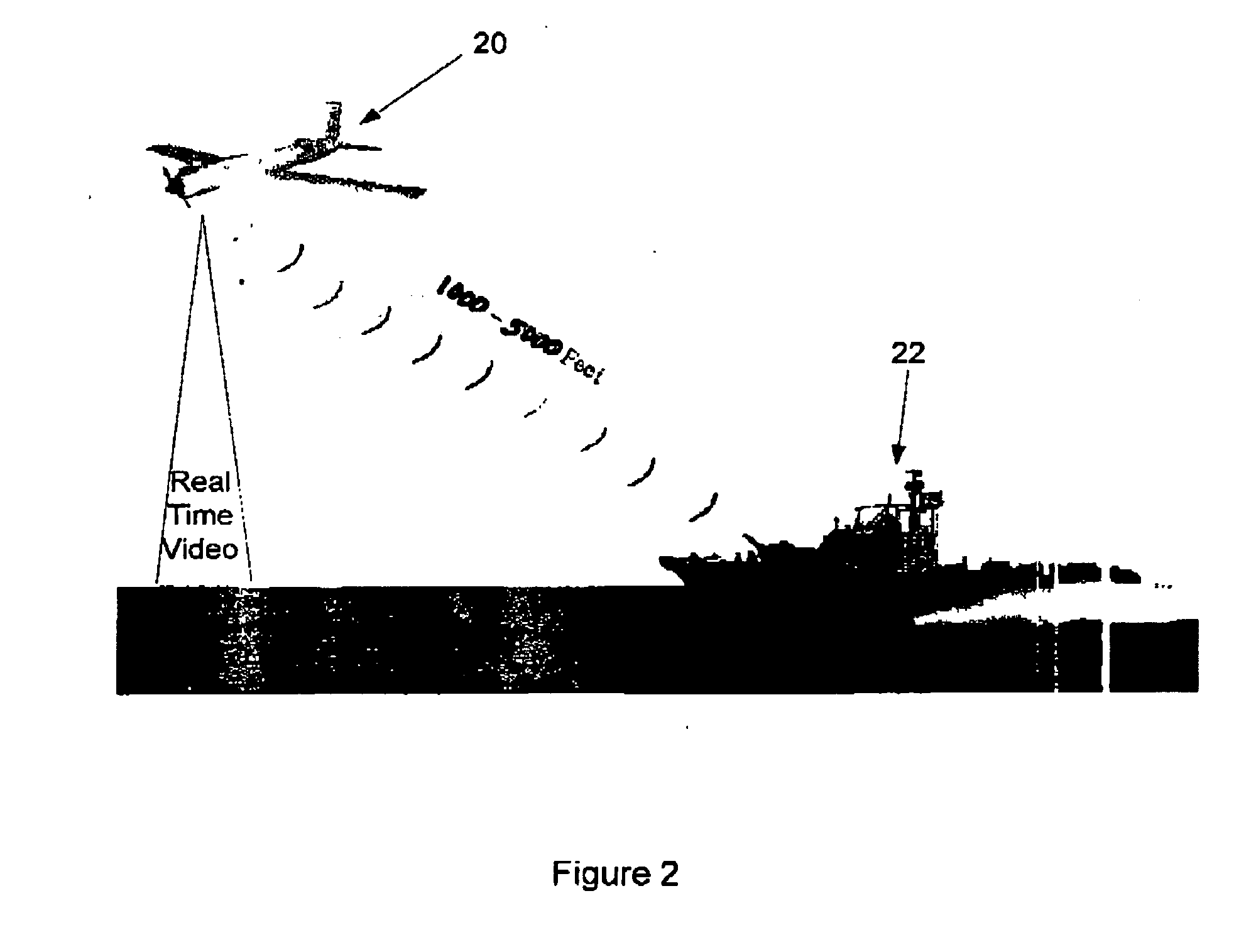
The present invention provides methods and apparatuses for surveillance of a convoy, which includes at least one ground vehicle. An unmanned aerial vehicle (UAV) operates as a satellite vehicle and obtains images around the convoy's position to provide information about potential hostile activity. The UAV maintains a curvilinear path around the convoy as instructed by one of the convoy vehicles. The controlling convoy vehicle processes position and velocity information regarding the UAV and the convoy to determine control variables, which are sent to the UAV. The surveillance vehicle follows a path with respect to the convoy and sends position and velocity information to a control center, which sends instructions to the surveillance vehicle to maintain its path. The path of the surveillance vehicle may be changed to provide evasive measures to avoid an attack. The convoy may include at least one ground vehicle, at least one ship or other water vehicle, or another ship or submarine for protecting the water vehicle. The invention allows for effective surveillance of a convoy and provides valuable information for potential threats.

Problems solved by technology

Surveillance may be provided by an aircraft or by a satellite that executes a single pass over a large region and is typically restricted in the time of surveillance coverage.
The area of interest (e.g., corresponding to troop movement) may be a small subset of the region of surveillance and may consequently require arduous analysis of all of the collected data.

Method used


Image

  • Unmanned vehicle
  • Unmanned vehicle
  • Unmanned vehicle

Examples


Embodiment Construction

System Overview

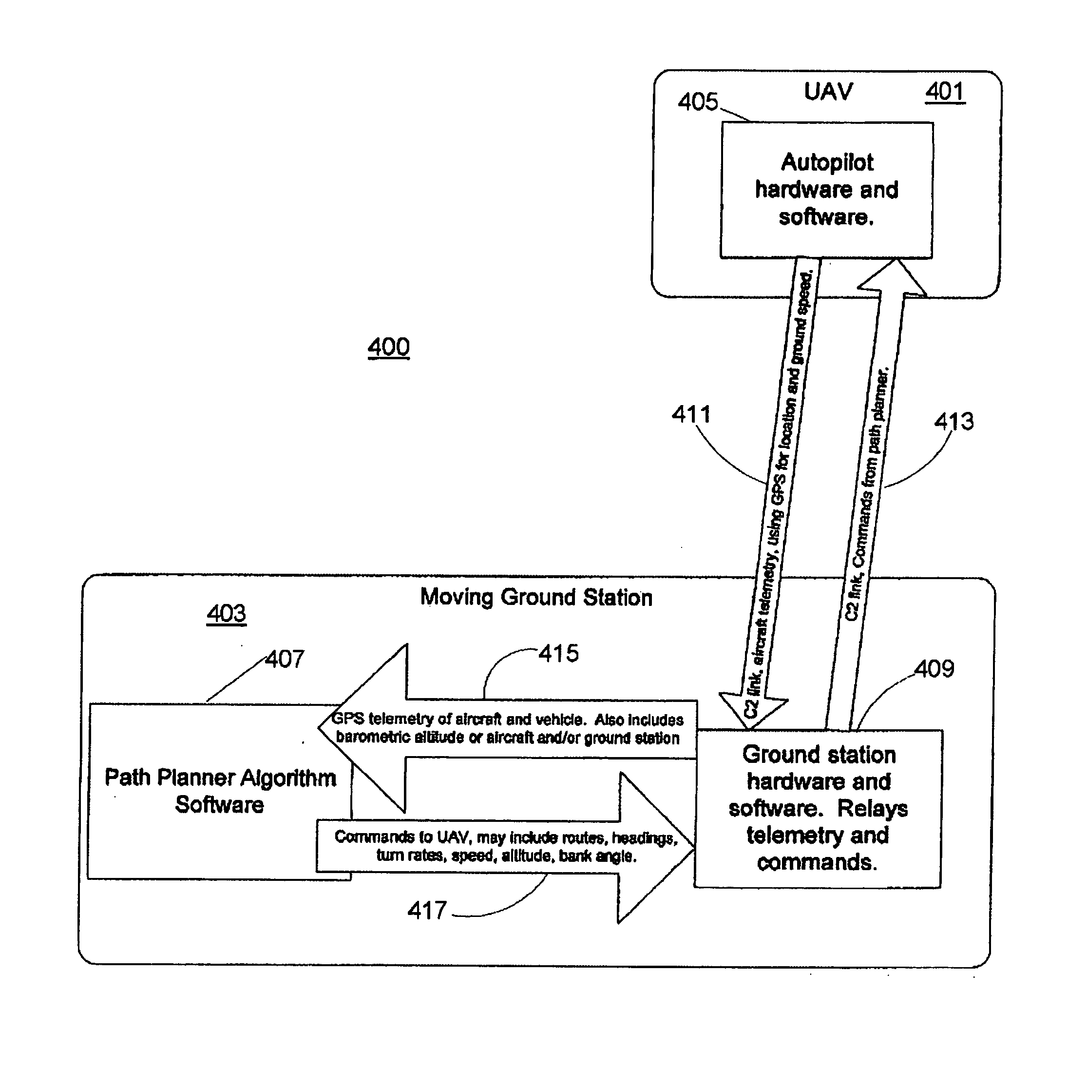
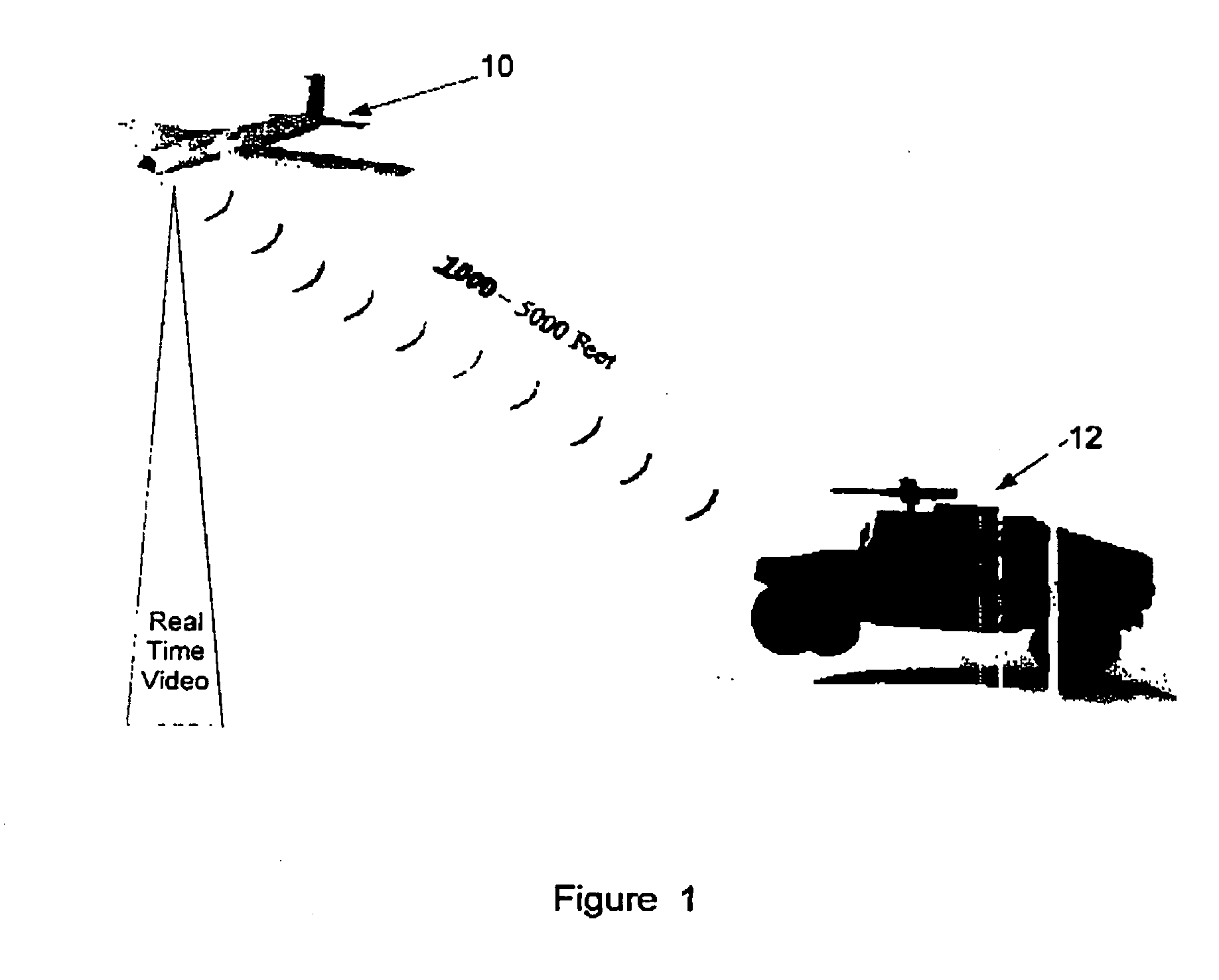
[0034]FIG. 1 shows an unmanned aerial vehicle (UAV) 10 flying in front of a vehicle 12. Vehicle 12 may monitor the position of UAV 10 and communicate with the flight control system of UAV 10 to cause UAV 10 to constantly remain in front of vehicle 12 and provide overhead surveillance. The embodiment may also cause UAV 10 to maintain a path around vehicle 12 so that images may be obtained in front of, behind, and on the flanks of vehicle 12. In one embodiment, UAV 10 includes a global positioning system (GPS) receiver and transmits current coordinates to vehicle 12. Vehicle 12 may also include a GPS receiver and may use information received from both GPS receivers to calculate the trajectory of UAV 10. This information may then be used to calculate one or more way points to keep UAV 10 on a desired path. As described herein, a convoy may comprise at least one vehicle, e.g., vehicle 12. One or more of the vehicles in the convoy may control UAV 10. Vehicle 12 may trans...


PUM


Abstract

Methods and apparatuses provide surveillance of a convoy. At least one unmanned aerial vehicle (UAV) obtains images around the convoy's position to provide information about potential hostile activity while the UAV follows a generally curvilinear path around the convoy as instructed by one of the convoy vehicles. Path planner algorithm software is executed by the controlling convoy vehicle in which position and velocity information regarding the unmanned aerial vehicle and the convoy are processed to determine values of control variables. The determined values are sent to the unmanned aerial vehicle over a wireless communications channel. The path of the surveillance vehicle may be changed in order to provide evasive measures to avoid an attack on the surveillance vehicle by an adversary.

Description

[0001] This application claims priority to provisional U.S. Application No. 60 / 529,388 (“Unmanned Vehicle”), filed Dec. 12, 2003.FIELD OF THE INVENTION [0002] Aspects of the present invention relate to unmanned vehicles. In particular, aspects of the invention provide unmanned vehicles that autonomously track vehicles and / or other unmanned vehicles. BACKGROUND OF THE INVENTION [0003] In order to protect both material and human assets, it is important to be cognizant of potential hostile activity that may endanger the assets. There are numerous scenarios that may encounter hostile activity, including troop movement and ship maneuvers. Effective surveillance provides information (e.g., images) of potential hostile activity near the protected assets. [0004] Surveillance may be provided by an aircraft or by a satellite that executes a single pass over a large region and is typically restricted in the time of surveillance coverage. Subsequent observations may be limited to the next pass ...

Claims


Application Information

Patent Timeline
Patent Type & Authority Applications(United States)
IPC IPC(8): G01C21/26G01S19/48B64C15/00B64C39/02
CPCB64C2201/121B64C2201/123B64C2201/126B64C2201/127B64C2201/141B64C2201/146B64C2201/208B64C39/024B64C2201/021B64C2201/044B64C2201/104B64C2201/205G05D1/0094B64U50/11B64U2201/10B64U80/84B64U80/86B64U2201/20B64U2101/17B64U2101/31B64U2101/18
Inventor MULLIGAN, ANTHONY C.TROUDT, CHRISTOPHER D.DOUGLAS, JASON MICHAEL K.
Owner RAYTHEON CO
Learn More