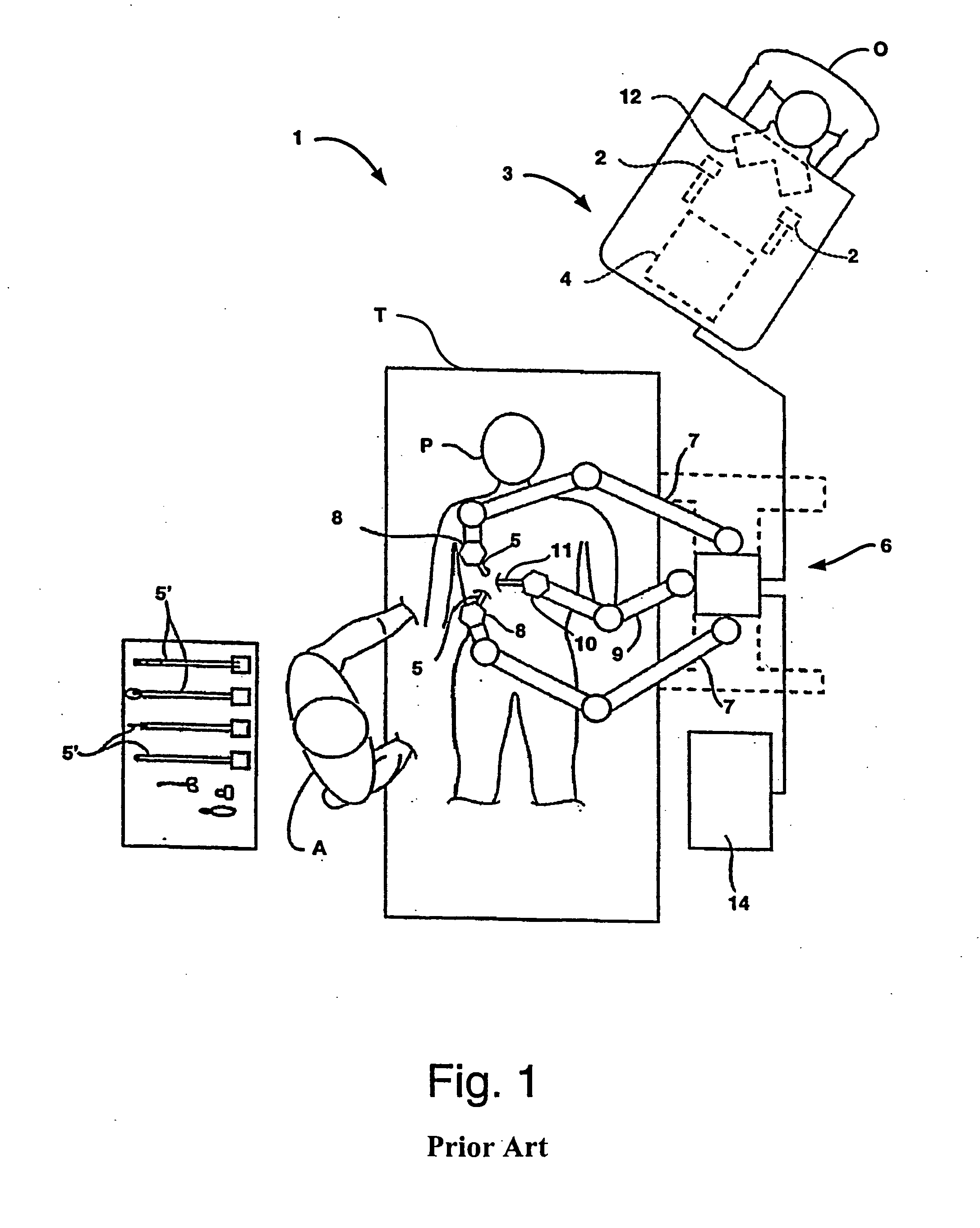
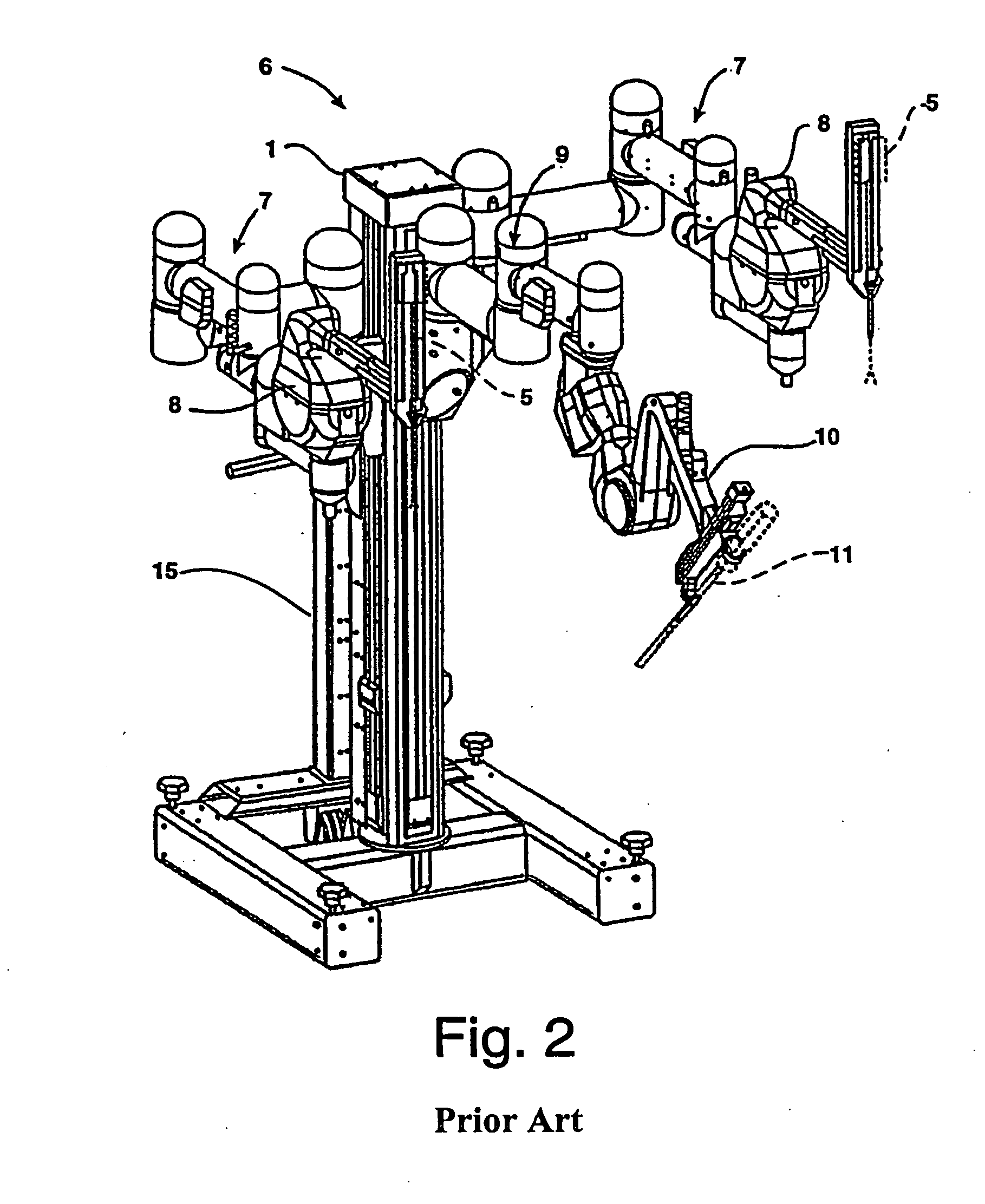
[0007] The present invention is generally related to medical, surgical, and / or robotic devices and systems. In particular, the present invention is directed to improved remote center manipulators used to support a
surgical instrument and provide a center of spherical rotation, remote from any bearings or mechanical supports, at a desired location of the instrument during minimally invasive
robotic surgery. The remote center
manipulator constrains the instrument to move around a fixed center of rotation, which is preferably coincident with an entry incision in a patient, such as the patient's
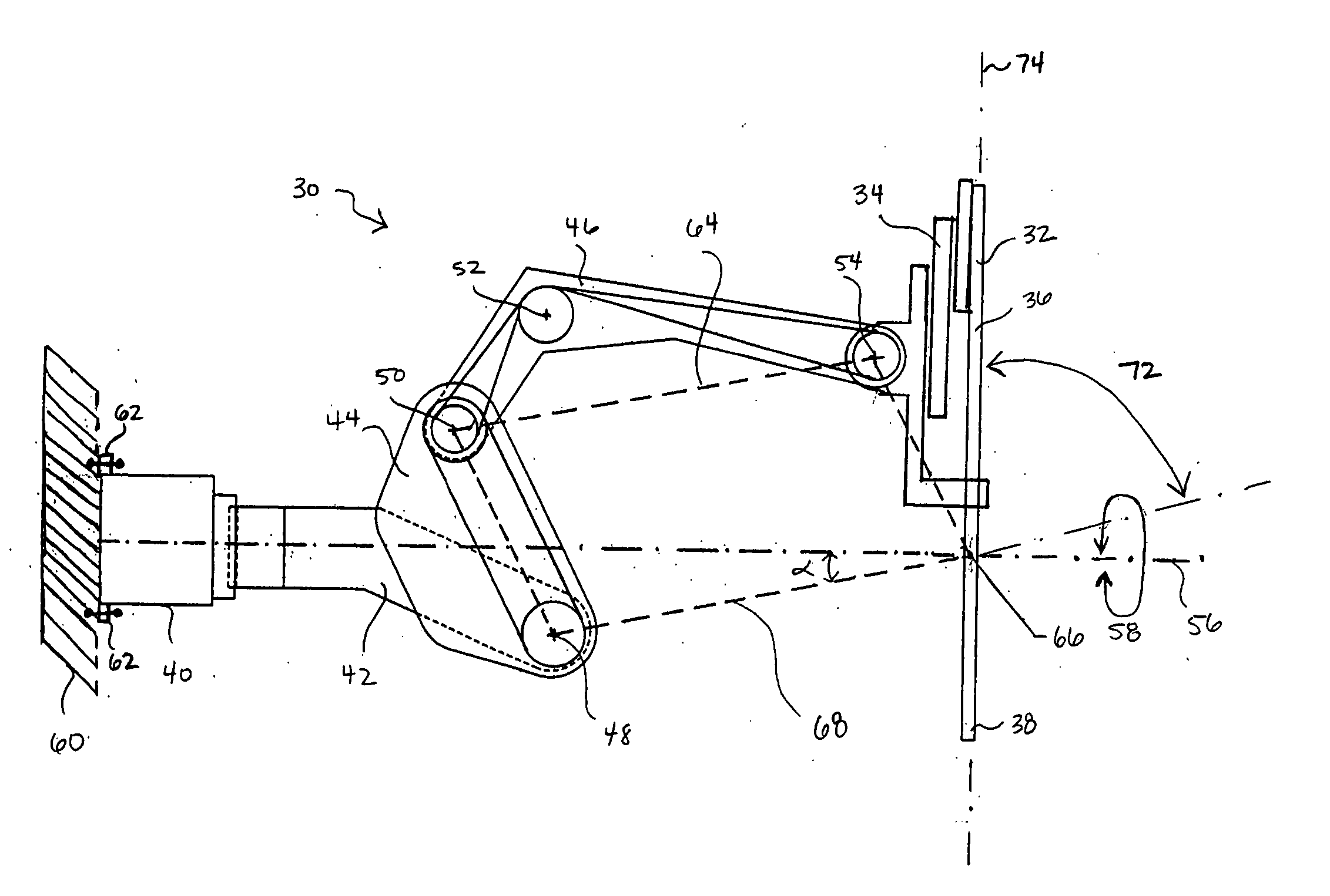
abdominal wall. In an exemplary embodiment, the invention provides an offset remote center
parallelogram manipulator linkage
assembly which constrains a position of a surgical instrument during minimally invasive robotic
surgery. The improved remote center manipulator advantageously enhances the range of instrument motion along first and second axes while at the same time reduces the overall complexity, size, and physical weight of the robotic surgical
system. Such advantages in turn enhance the efficiency and ease of use of such robotic surgical systems.
[0009] The first side of the
parallelogram is angularly offset from the first axis by at least 2 degrees, preferably by 10 degrees. Generally, the first side of the parallelogram is angularly offset from the first axis in a range from about 2 degrees to about 45 degrees, preferably in a range from about 2 degrees to about 35 degrees. The first side of the parallelogram may sometimes extend beneath the first axis, generally at least one side of the parallelogram extends beneath the first axis. The manipulator provides an improved range of shaft motion that is greater than ±90 degrees along the first axis, preferably greater than ±95 degrees along the first axis. In particular, the cantilevered parallelogram linkage base provides shaft motion in a range from ±168 degrees along the first axis, wherein the first axis is sometimes referred to as a
yaw axis. Advantageously, the offset articulate linkage
assembly provides an improved range of shaft motion that is greater than ±55 degrees along a second axis, preferably greater than ±60 degrees along the second axis. Generally, the offset articulate linkage assembly provides improved shaft motion in a range from ±75 degrees along the second axis, wherein the second axis is sometimes referred to as a
pitch axis.
[0010] Preferably, at least one of the links is bent at an angle so as to provide clearance for another link to rest on the bent link. This clearance prevents inter-linkage collisions so as to further allow for an improved range of
pitch motion. For example, the link may be bent at an angle of about 22 degrees. The manipulator may not be balanced in at least one degree of freedom. As such, a
brake system may be coupled to the articulate linkage assembly. The
brake system releasably inhibits articulation of at least one of the joints. Preferably, the plurality of links and joints comprise at least one
pulley and at least one flexible element coupled to the
pulley that is configured to constrain shaft motion relative to the center of rotation. In one embodiment, the plurality of links and joints comprise a linkage having six pulleys and four belts. The plurality of links and joints are driven by a
servomechanism. The plurality of links and the parallelogram linkage base may be offset in different planes so as to reduce the possibility of inter-linkage collisions. The plurality of links and the instrument holder however may be located in the same plane.
[0011] In general, the articulate linkage assembly is configured to constrain shaft motion relative to the center of rotation. As such, the shaft is maintained substantially aligned through the center of rotation as the shaft is pivotally moved in at least one degree of freedom. Preferably, the center of rotation is aligned with the incision point to the internal
surgical site, for example, with a trocar or cannula at an
abdominal wall during
laparoscopic surgery. As such, an end
effector of the surgical instrument can be positioned safely by moving the proximal end of the shaft using the offset remote center robotic manipulator without imposing dangerous forces against the
abdominal wall.
[0013] The first pivot of the parallelogram is angularly offset from the first axis by at least 2 degrees, preferably by 10 degrees. Generally, the first pivot of the parallelogram is angularly offset from the first axis in a range from about 2 degrees to about 45 degrees, preferably in a range from about 2 degrees to about 35 degrees. The first pivot of the parallelogram may sometimes extend beneath the first axis, generally at least one pivot of the parallelogram extends beneath the first axis. The manipulator provides shaft motion in a range greater than ±90 degrees along the first axis, preferably greater than ±95 degrees along the first axis. In particular, the cantilevered parallelogram linkage base provides improved shaft motion in a range from ±168 degrees along the first axis, e.g.,
yaw axis. Advantageously, the offset parallelogram and bent link together provide shaft motion in a range greater than ±55 degrees along a second axis, preferably greater than ±60 degrees along the second axis. Typically, the offset parallelogram and bent link provide improved shaft motion in a range from ±75 degrees along the second axis, e.g.,
pitch axis.
[0017] In still another aspect of the present invention, a method for performing minimally invasive robotic
surgery within a
body cavity of a patient employing a surgical instrument is provided. The surgical instrument coupleable to an instrument holder during minimally invasive robotic surgery includes an elongate shaft. The shaft has a distal working end configured for
insertion through an incision in a body wall into a
body cavity of a patient. The method comprises providing an offset articulate linkage assembly as described above. At least the distal working end of the instrument shaft is introduced through the incision into the
body cavity. At least the shaft of the instrument is pivotally moved in at least one degree of freedom while at least a portion of the distal working end is within the body cavity. The offset articulate linkage assembly constrains lateral motion of the shaft to pivotal motion about the center of rotation so that the shaft is maintained substantially aligned through the center of rotation.


