
Collapsible step and extension ladder

a ladder and step technology, applied in the field of collapsible ladders, can solve the problems of complicated design and costly manufacturing, and achieve the effects of preventing tipping and damage to the fascia siding or roof of a home, preventing damage to the fascia, and easy material hauling

Inactive Publication Date: 2006-04-06
JAFFE HERBERT
View PDF4 Cites 1 Cited by
  • Summary
  • Abstract
  • Description
  • Claims
  • Application Information

AI Technical Summary

Benefits of technology

[0028] It is an object of the present invention to provide a ladder that can be disassembled into easily handled sections.
[0030] An object of the present invention is to provide an extension ladder which includes both an upper and a lower stabilizer to prevent tipping and damage to the fascia siding or roof of a home.
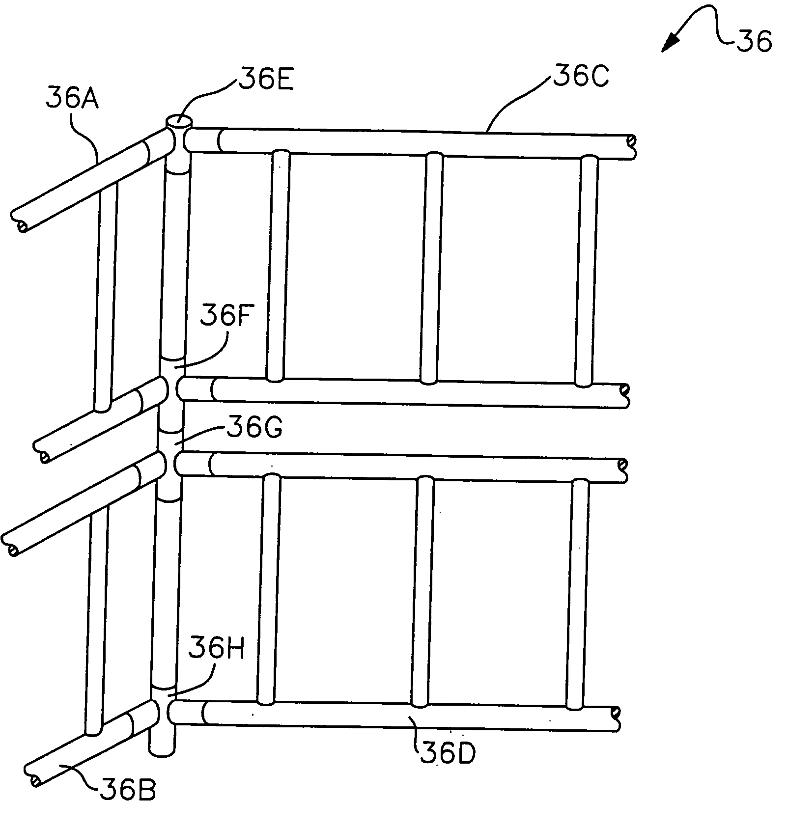
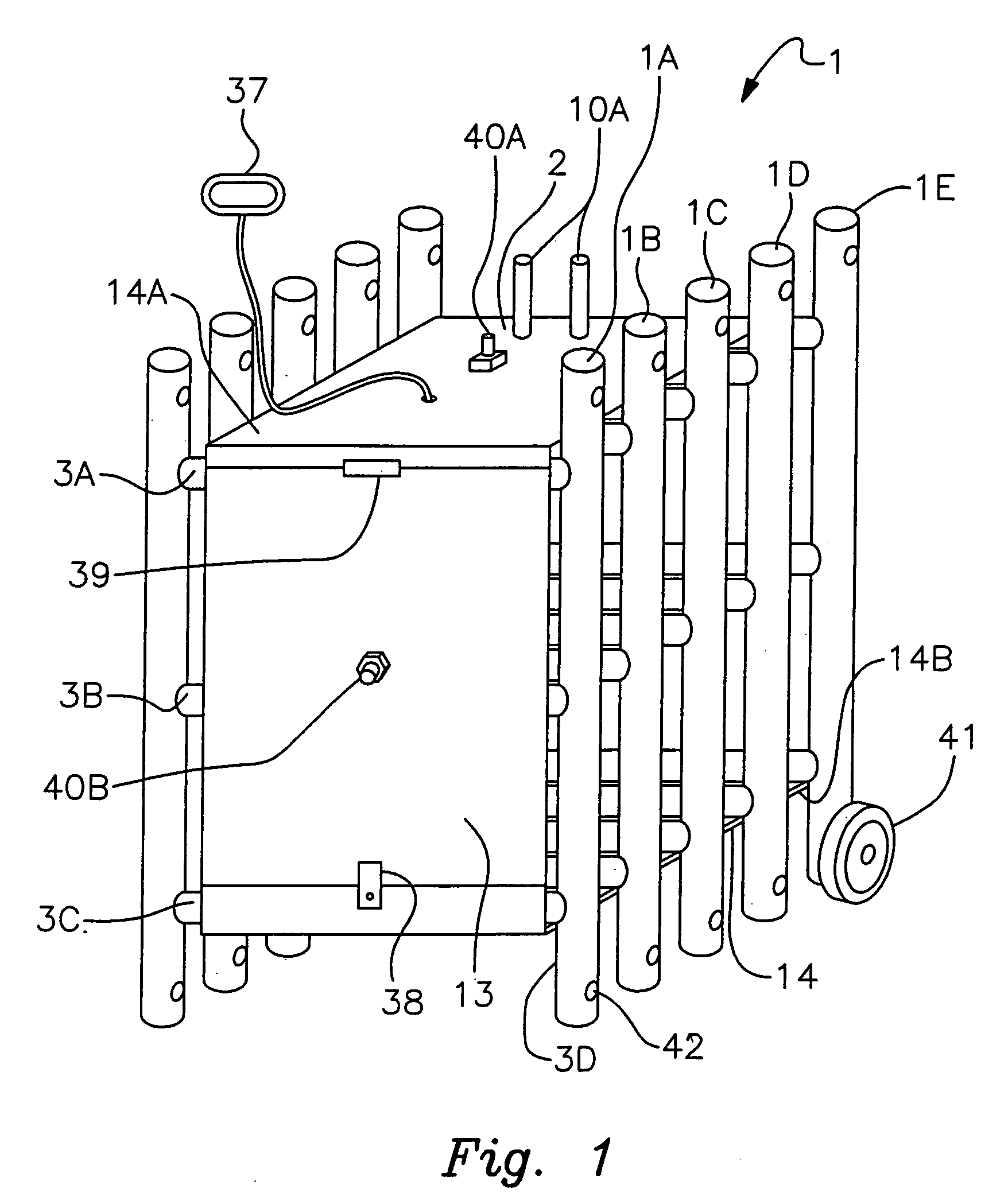
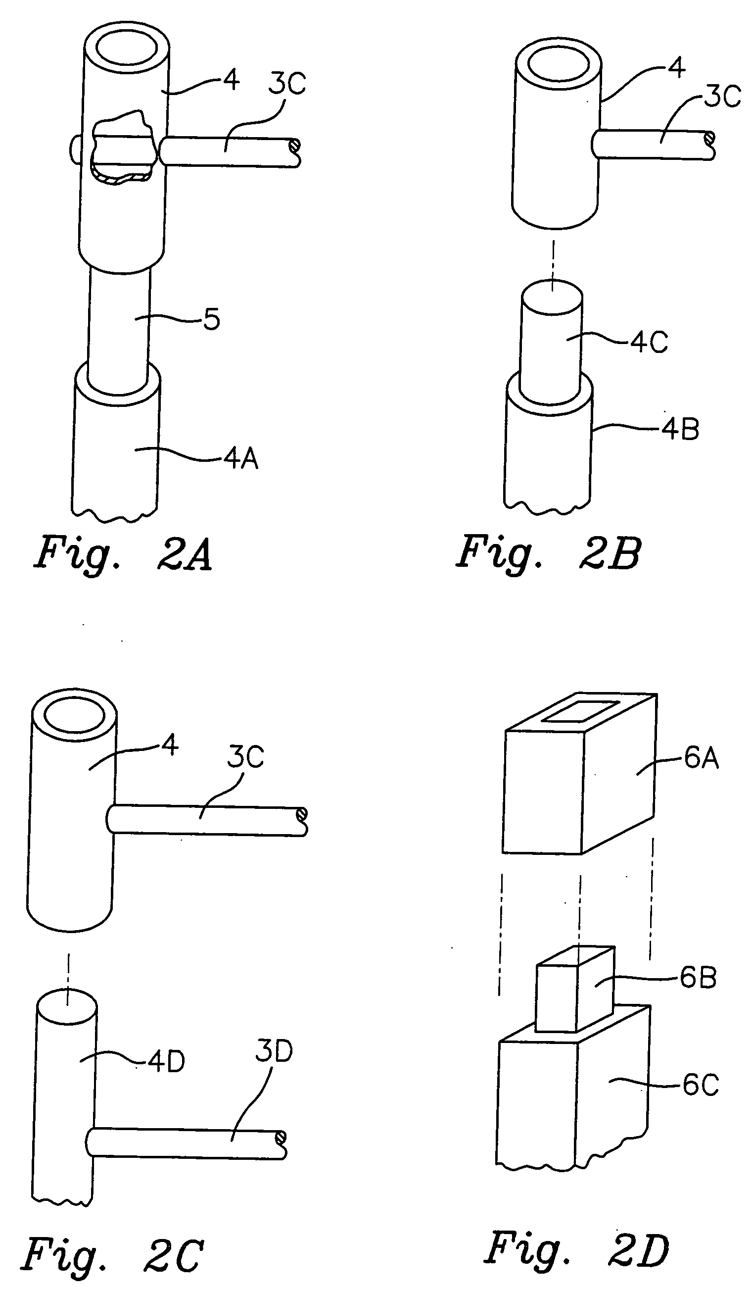
[0032] The present invention is a ladder formed of easily storable sections that may be quickly assembled to form a step ladder or an extension ladder, a hoist, scaffolding or a fence. The base and top of the extension ladder include separate stabilization sections which prevent the ladder from tipping or from damaging the fascia. The upper stabilizer can be easily converted into a hoist for hauling material to the top of the ladder.

Problems solved by technology

This is a complicated, costly design to manufacture.

Method used


Image

  • Collapsible step and extension ladder
  • Collapsible step and extension ladder
  • Collapsible step and extension ladder

Examples


first embodiment

[0059] In the invention, the brackets are attached to the platform and surround at least the top of the extension arms. The locking screws may be either thumb screws to grip the extension arms or screws which penetrate the extension arms for a more permanent arrangement. The brackets are generally placed at the corners of the platform to provide maximum strength. The platform lies between the extension arms and the backboard rest against the collars.

[0060] The use of the hoist is shown in FIG. 6. This Figure is a side elevation view of the ladder of the present invention used with the hoist of FIG. 5A. This Figure shows a wall 9, a ground line 12, a ladder with a rail 22B resting on the ground at its bottom and against the wall 9 at its top, and the hoist shown in FIG. 5A. The components of the hoist that can be seen in this Figure include the extension arm 19A, the collar 17A, and the back stop 23B. Added to the ladder is a pulley 28 over which is placed a line 27. One end of the l...

second embodiment

[0063] In a second embodiment, the hoist 31 of FIG. 5C is almost identical to that of FIG. 5A except the left and right skids 26A and 26B are substituted for collars 17A and 17B. Only right skid 26B can be seen in FIG. 6. The skids are longer than the collars to that they can ride on the ladder rungs and the sled formed by the skids is narrower than the width of the ladder. therwise the operation of the two hoists is identical.

[0064] A variation which is within the spirit and scope of the invention is to include wheels on the hoist to facilitate raising the hoist on the ladder. The wheels include a ratchet which brake to prevent the hoist from going down unintentionally. The wheels may include a groove to grip the rails or may be doubled with one wheel on each side of a rail to grip the rails and prevent the hoist from shifting off of the ladder. The hoist ratchet is released after removing the load or when it is desired to bring a load down the ladder. A further improvement is to i...


PUM


Abstract

A ladder formed of easily storable sections is quickly assembled to form a step ladder, extension ladder, hoist, scaffolding or fence. The base and top of the extension ladder include separate stabilizers which prevent the ladder from tipping or from damaging the fascia. The upper stabilizer may be converted to perform a second function as a hoist, substantially reducing the cost and space needed for storage of the invention.

Description

BACKGROUND [0001] 1. Field [0002] The present invention relates to collapsible ladders and more particular to such ladders which may be disassembled into separate sections. [0003] 2. Prior Art [0004] There are prior art ladders that are collapsible as can be seen from the following three patents. [0005] U.S. Pat. No. 3,993,714 is a ladder that can be assembled from sections; however, it is designed for use in climbing poles and must be lashed to the pole for support. [0006] U.S. Pat. No. 4,493,392 is a collapsible ladder that folds in on itself, but does not separate into sections. The whole weight of the ladder must be carried at all times when it is moved, even when it has been collapsed in preparation to be moved into storage. [0007] U.S. Pat. No. 5,645,140 shows a collapsible ladder in which the supports running from rung to rung are designed to telescope into the support below. This is a complicated, costly design to manufacture. The ladder is never disassembled into sections a...

Claims


Application Information

Patent Timeline
Patent Type & Authority Applications(United States)
IPC IPC(8): E04G7/00
CPCE06C1/10E06C1/18E06C7/12E06C7/42E06C7/48
Inventor JAFFE, HERBERT
Owner JAFFE HERBERT
Learn More