
Steering wheel for motor vehicles

a technology for steering wheels and motor vehicles, applied in the direction of anti-theft devices, navigation instruments, instruments, etc., can solve the problems of increasing driver information, increasing concentration, and limited information capacity of drivers, so as to reduce attention and ease of perception

Inactive Publication Date: 2006-04-06
JOYSON SAFETY SYST GERMANY GMBH
View PDF2 Cites 67 Cited by
  • Summary
  • Abstract
  • Description
  • Claims
  • Application Information

AI Technical Summary

Benefits of technology

[0007] The invention is therefore based on the object of making information, such as, for example, information of a driver guidance system or of a driver assistance system, available to the driver in such a way that he can easily perceive it, and that the driver can also input information for the systems or for a telephone without having to significantly reduce his attentiveness in road traffic.
[0011] The arrangement of elements on the steering wheel for providing the driver with information has the advantage that there is virtually no effect on the attentiveness of the driver in road traffic since the steering wheel is also in his field of vision in any case when he is driving.
[0018] It is expedient that the arrows or points can be actuated as a function of the distance from the location of a change in direction of travel in such a way that they light up to different degrees or have different colors. As a result, the driver can be informed in good time of a necessary change in direction of travel. The fact that the location of the change in direction of travel has been reached can be achieved by an actuation process which triggers flashing of the arrows or points and / or a change in their color from green to red.

Problems solved by technology

The increasing complexity of road traffic requires increasing driver information about his surroundings.
On the other hand, the capacity of the driver to take in information is limited.
The driver also has to concentrate on essential driving functions, which also requires increasing concentration because of the increasing amount of road traffic.
The disadvantage of the visual systems is that they are arranged in the dashboard on the other side of the driver, so that in particular when the driver is considering the display of a driver guidance system he cannot pay attention to the road traffic.

Method used


Image

  • Steering wheel for motor vehicles
  • Steering wheel for motor vehicles
  • Steering wheel for motor vehicles

Examples


Embodiment Construction

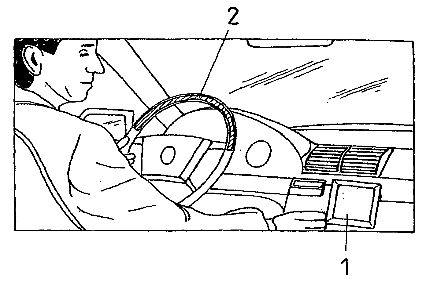
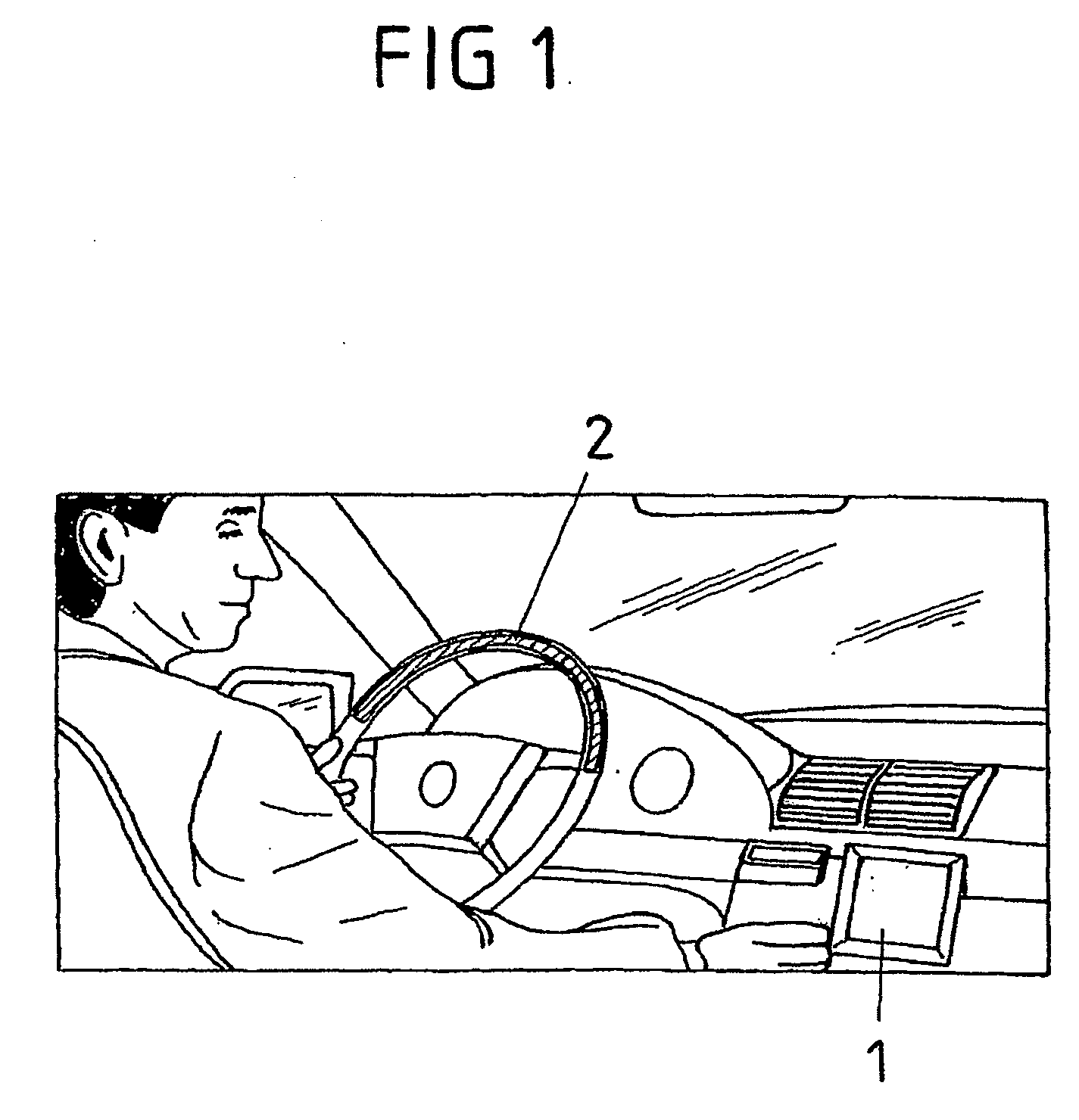
[0044]FIG. 1 shows the standard situation for the application of a conventional driver guidance system. The latter has a display 1 which is arranged to the side of the driver in the dashboard. When this display is considered, the driver must therefore inevitably look to the side, so that during this time he cannot pay attention to the road traffic. The risk of accident is thus increased considerably. This state is particularly critical if the quantity of information which is conveyed to the driver will increase in future. However, the steering wheel in FIG. 1 already has an illuminated strip 2 for indicating hazardous situations.

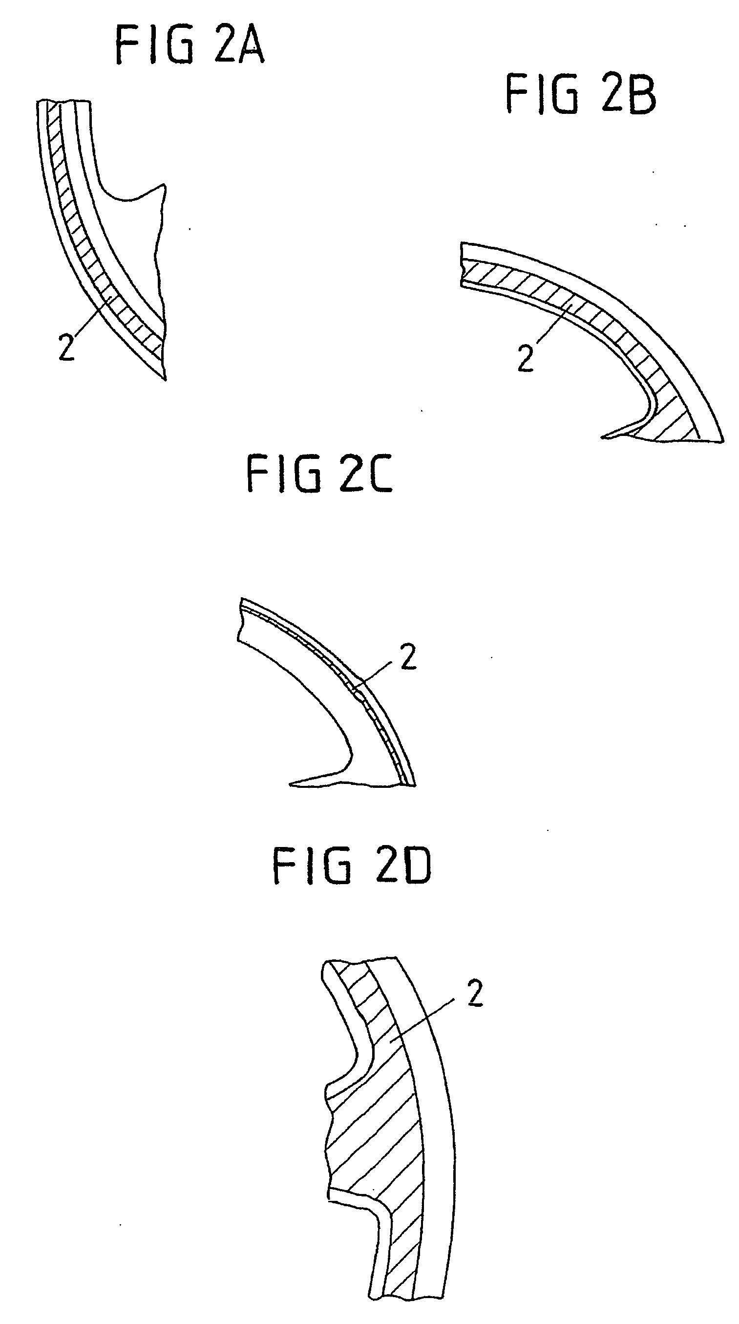
[0045]FIGS. 2A-2D show different embodiments of the strips 2. The strips 2 in the embodiment in FIG. 2C are narrower than in the other embodiments. These strips are suitable for indicating hazardous situations by virtue of the fact that they change color, for example, from green to red or change their intensity. These strips may, for example, by composed of...


PUM


Abstract

A steering wheel for motor vehicles is disclosed. The aim of the steering wheel is to supply information from a driver guidance system or a driver assistance system to a driver in such a way that said information is easily received and that the driver can also input information for said systems or for a telephone, without having to divert his or her attention from the traffic. To achieve this, the steering wheel is configured as a communication interface for the driver.

Description

CROSS REFERENCE TO RELATED APPLICATIONS [0001] This is a continuation application of prior application number PCT / DE2004 / 000627, filed Mar. 22, 2004 and claims the benefit under 35 U.S.C. §119 of prior foreign applications number DE 103 16 738.2, filed Apr. 4, 2003 and number DE 103 52 733.8, filed Nov. 6, 2003.FIELD OF THE INVENTION [0002] The invention relates to a steering wheel for motor vehicles. BACKGROUND OF THE INVENTION [0003] Motor vehicle steering wheels are known which have both an air bag and switches or push button keys with which it is possible, for example, to set a station on the radio or even to set its volume without operating the radio itself, which is usually mounted in the dashboard to the side of the driver, and without thus being distracted from the road traffic. [0004] The increasing complexity of road traffic requires increasing driver information about his surroundings. The quantity of information which is transmitted to the driver of the vehicle is theref...

Claims


Application Information

Patent Timeline
Patent Type & Authority Applications(United States)
IPC IPC(8): B62D5/04B60K35/10B60Q9/00B60R11/00B60R11/02B62D1/04B62D1/06B62D15/02G01C21/36G08G1/16
CPCB60K37/06B60K2350/928B60Q9/00B60R11/0264B60R2011/001B62D1/046B62D1/06B62D15/029G01C21/265G01C21/3652G01C21/3688G08G1/16G08G1/166G01C21/3632G01C21/3661B60K35/10B60K35/60B60K2360/782
Inventor MEISSNER, DIRK
Owner JOYSON SAFETY SYST GERMANY GMBH
Learn More