
Radiographic detector docking station with dynamic environmental control

a technology of dynamic environmental control and radiographic detector, which is applied in the field of diagnostic imaging, can solve the problems of increasing the power of electronic components to carry out the complex process, “hot spots, external surfaces of x-ray detectors, etc., and achieve the effect of reducing the differen

Inactive Publication Date: 2006-04-06
GENERAL ELECTRIC CO
View PDF46 Cites 84 Cited by
  • Summary
  • Abstract
  • Description
  • Claims
  • Application Information

AI Technical Summary

Benefits of technology

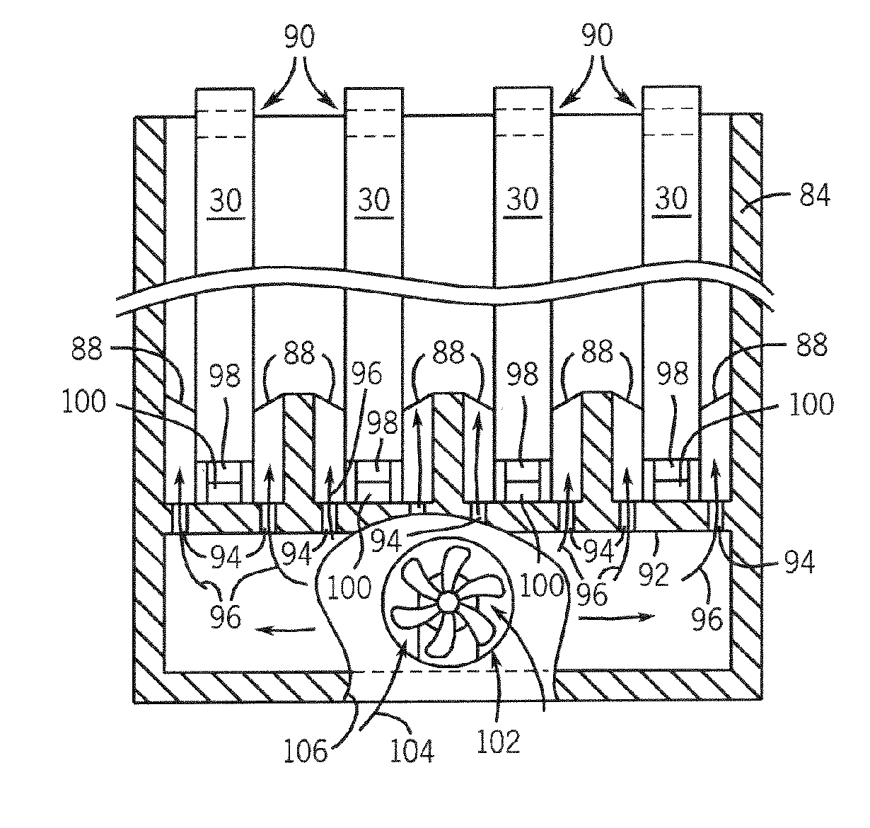
[0015] In accordance with another aspect, an x-ray detector storage apparatus is presented and includes a receptacle sized to receive an x-ray detector during non-use of the x-ray detector. The apparatus also has a temperature control interface connected to the receptacle and configured to provide feedback as to a temperature of an x-ray detector when the x-ray detector is disposed within the receptacle. A thermal exchange system is configured to regulate the temperature of an x-ray detector when the x-ray detector is disposed within the receptacle. The apparatus further includes a controller operationally connected to receive the feedback and control the thermal exchange system to reduce a difference between the temperature of an x-ray detector disposed in the receptacle and a desired temperature.

Problems solved by technology

These electronic components are increasingly requiring more power to carry out the complex processes required for operation of the x-ray detector, e.g. data acquisition and data readout.
These increased power requirements can expose the x-ray detector to increased thermal loads thereby resulting in “hot spots” on an external surface of the x-ray detector.
As such, designing the x-ray detector to have an exhaust port that would allow the ingress of cleaning agents is not practicable.
Other proposed solutions include radiation and free convection; however, both are inadequate in responsively regulating the temperature of an x-ray detector.
Similarly, free convection does not remove a sufficient amount of heat to maintain the x-ray detector at a required temperature in a responsive manner.
Free convection is capable of removing the heat but the time required to do so can be lengthy, resulting in considerable down-time of the x-ray detector.
This can be problematic for high use facilities such as emergency rooms, triage centers, and the like where turnaround time can be critical to diagnosing a patient.
Also, these proposed solutions are solely concerned with dissipating heat from an x-ray detector, not maintaining the temperature of the x-ray detector within a prescribed temperature range.

Method used


Image

  • Radiographic detector docking station with dynamic environmental control
  • Radiographic detector docking station with dynamic environmental control
  • Radiographic detector docking station with dynamic environmental control

Examples


Embodiment Construction

[0034] The present invention will be described with respect to a flat panel, solid-state, indirect detection, and portable digital x-ray detector for use with a mobile x-ray imaging system. However, the present invention is equivalently applicable with other types of x-ray detectors including direct detection digital detectors. Additionally, the present invention may be used with stationary or fixed room x-ray imaging systems. Further, the present application makes reference to an imaging “subject” as well as an imaging “object”. These terms are not mutually exclusive and, as such, use of the terms is interchangeable and is not intended to limit the scope of the appending claims.

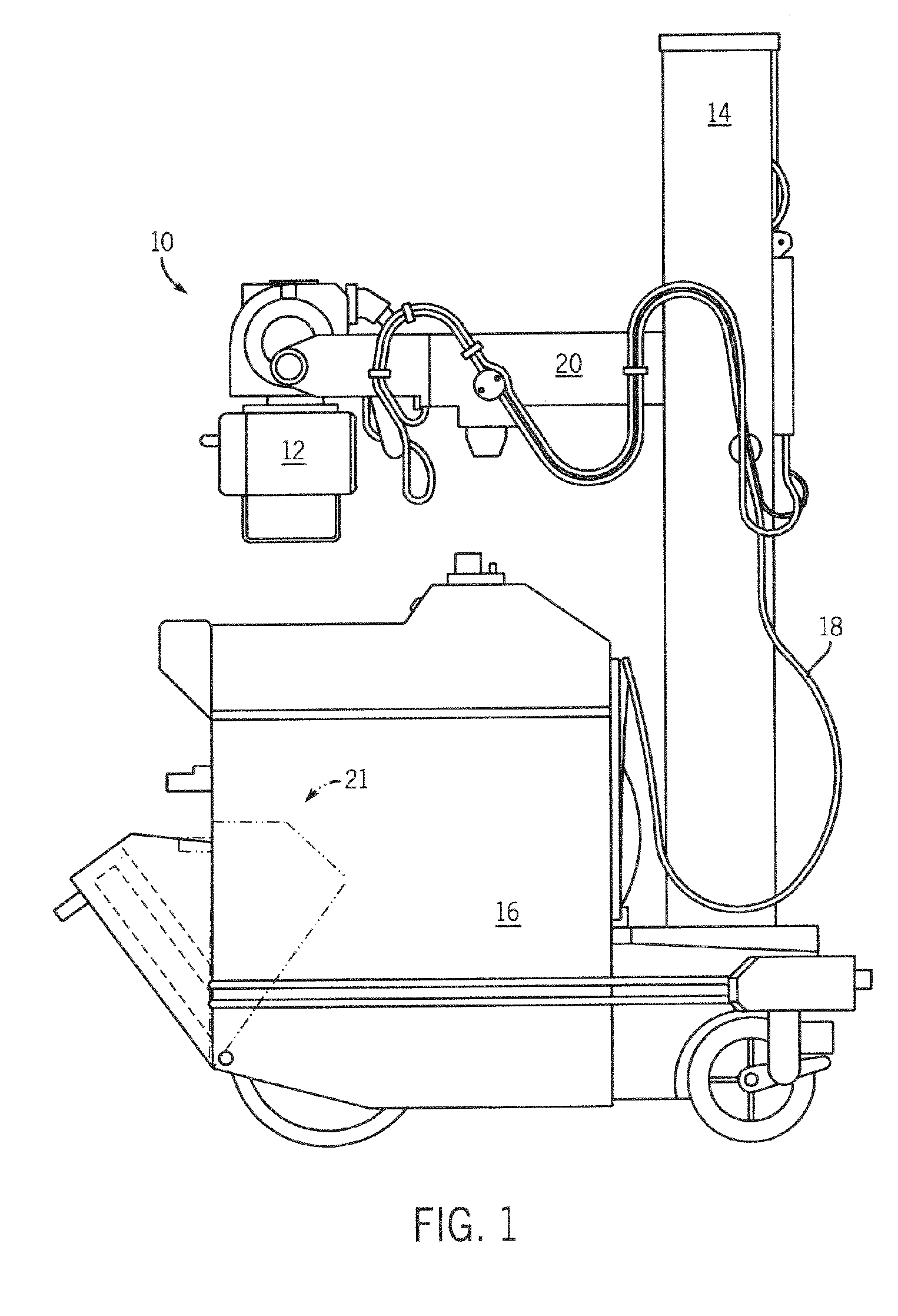
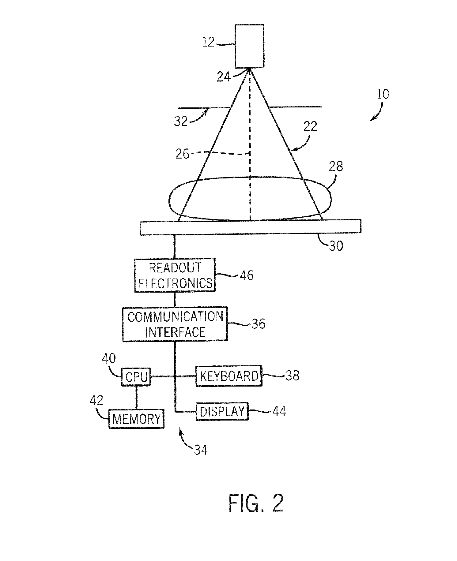
[0035] Referring now to FIG. 1, an exemplary mobile x-ray imaging system 10 applicable with a portable x-ray detector incorporating the present invention is shown. An x-ray source 12 is mounted or otherwise secured to an end of horizontal arm 20. Arm 20 allows the x-ray source 12 to be variably positioned a...


PUM


Abstract

A docking station for one or more x-ray detectors is disclosed and designed to secure an x-ray detector when not in use to limit exposure of an x-ray detector to drops, jars, and other potentially damaging incidents. The docking station may be equipped to regulate the temperature of a stored x-ray detector. Thermal regulation can be achieved passively or actively using convection, conduction, radiation, and other thermal transference principles. The docking station may also include an electronic interface that communicates with a stored x-ray detector such that thermal regulation may be achieved dynamically and responsively. The docking station may be free-standing or wall-mounted. The docking station may be remote from or integrated with an x-ray scanner. The docking station may also be equipped to charge / re-charge batteries of a stored x-ray detector.

Description

BACKGROUND OF THE INVENTION [0001] The present invention relates generally to diagnostic imaging and, more particularly, to a docking station that regulates the temperature of a stored detector. [0002] X-ray imaging is a non-invasive technique to capture images of medical patients for clinical diagnosis as well as inspect the contents of sealed containers, such as luggage, packages, and other parcels. To capture these images, an x-ray source irradiates a scan subject with a fan beam of x-rays. The x-rays are then attenuated as they pass through the scan subject. The degree of attenuation varies across the scan subject as a result of variances in the internal composition of the subject. The attenuated energy impinges upon an x-ray detector designed to convert the attenuating energy to a form usable in image reconstruction. A control system reads out electrical charge stored in the x-ray detector and generates a corresponding image. For a conventional, screen film detector, the image ...

Claims


Application Information

Patent Timeline
IPC IPC(8): F25B21/02F25D23/12
CPCG01T1/2018G01T1/2928
Inventor ERTEL, JASON R.
Owner GENERAL ELECTRIC CO
Learn More