
Liquid crystal panel and liquid crystal display apparatus

Active Publication Date: 2006-03-30
NITTO DENKO CORP
View PDF7 Cites 46 Cited by
  • Summary
  • Abstract
  • Description
  • Claims
  • Application Information

AI Technical Summary

Benefits of technology

[0008] The present invention has been made in view of solving the above problems, and an object of the present invention is to provide a liquid crystal panel having a liquid crystal cell with improved contrast ratio in an oblique direction. An other object of the present invention is to provide a liquid crystal panel and a liquid crystal display apparatus each having a liquid crystal cell with good display evenness without causing shift or unevenness in retardation values due to shrinkage stress of a polarizer or heat of backlight.
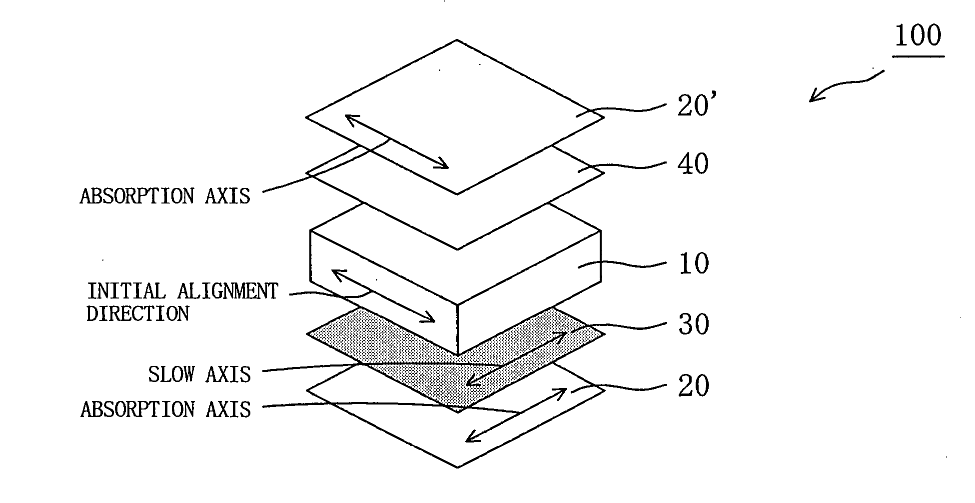
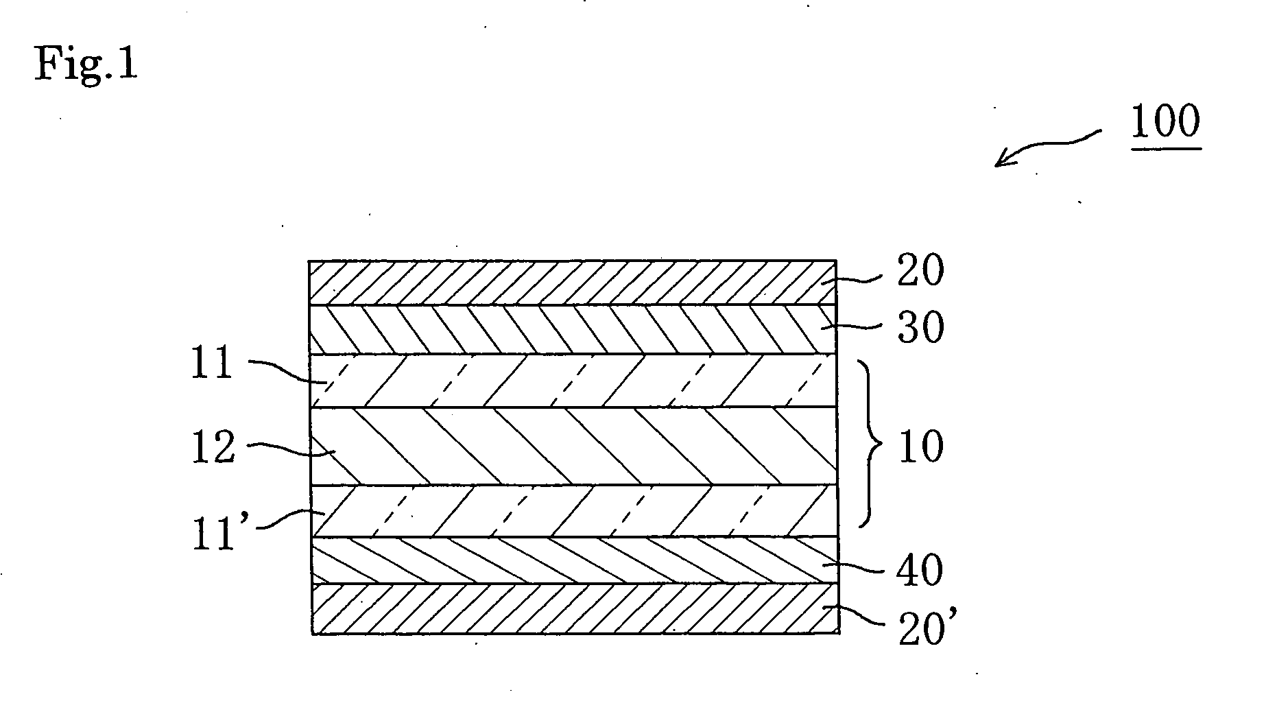
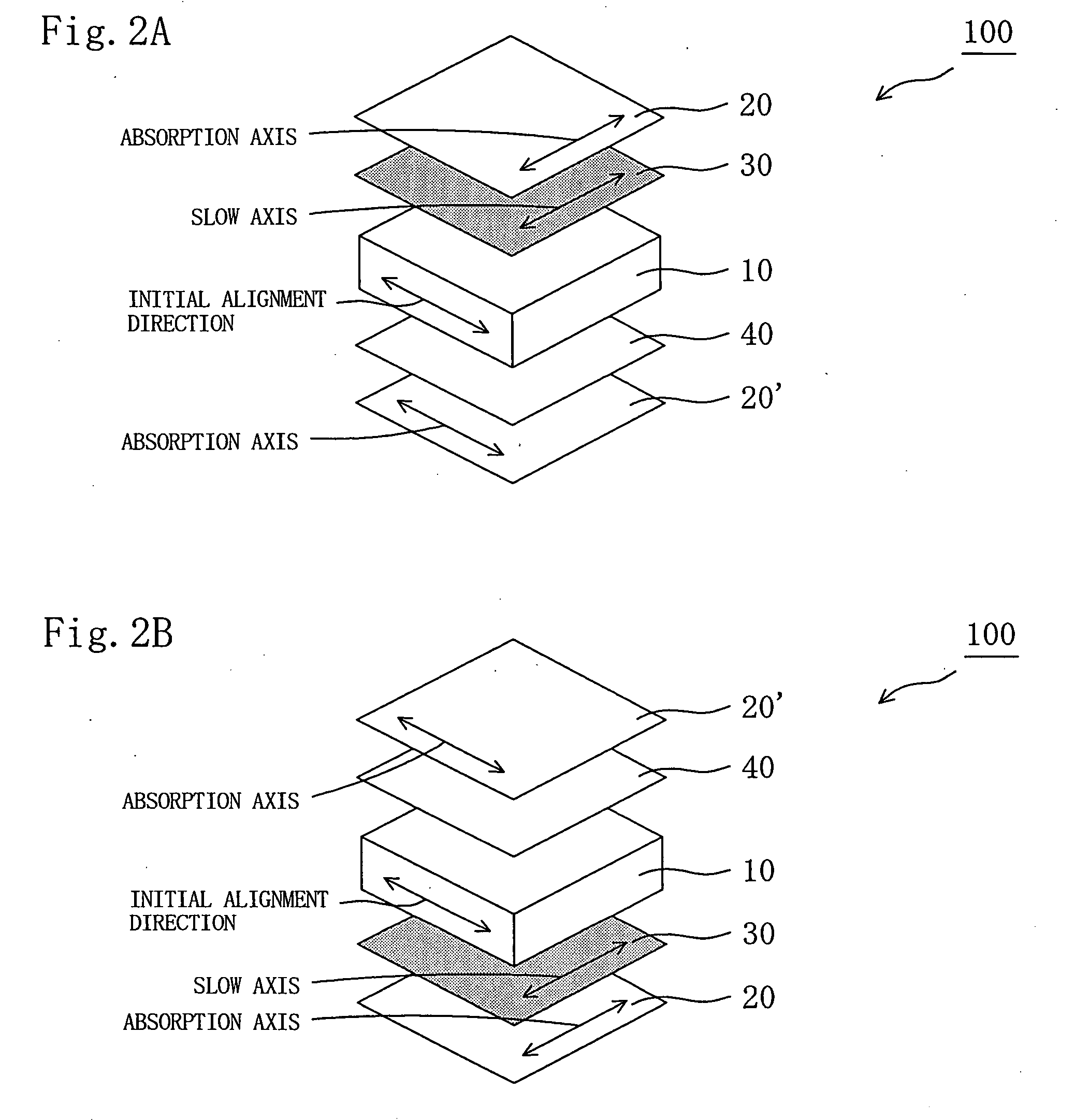
[0029] The liquid crystal panel of the present invention is provided with: the first optical element satisfying the below-indicated expressions (1) and (2) arranged between one polarizer and the liquid crystal cell; and the second optical element having substantially optical isotropy arranged between the other polarizer and the liquid crystal cell, to thereby enhance a contrast ratio of the liquid crystal display apparatus in an oblique direction. The first optical element of the present invention including the retardation film containing a norbornene-based resin has a small photoelastic coefficient, to thereby prevent unevenness in retardation values due to shrinkage stress of the polarizer or heat of backlight of the liquid crystal panel. No retardation film having a small photoelastic coefficient and having a refractive index profile of nx>nz>ny has been hitherto obtained. However, in the present invention, a shrinkable film having a predetermined shrinkage ratio is attached to one side or both sides of a polymer film containing a norbornene-based resin and the resultant is heat stretched, to thereby provide a retardation film having a small photoelastic coefficient and a refractive index profile of nx>nz>ny and satisfying the below-indicated expressions (1) and (2). As a result, good display properties of the liquid crystal display apparatus can be maintained for a long period of time. 240nm≦Re[590]≦350nm  (1) 0.20≦Rth[590] / Re[590]≦0.80  (2) (In the expressions (1) and (2), Re[590] and Rth[590] respectively represent in-plane retardation and thickness direction retardation values of the film measured by using light of a wavelength of 590 nm at 23° C.)

Problems solved by technology

A conventional liquid crystal display apparatus provided with a liquid crystal cell of IPS mode has a problem in that a contrast ratio of a screen viewed from an oblique direction at an angle of 45° (azimuth angle of 45°, 135°, 225°, or 315°) with respect to an absorption axis of a polarizer degrades.
However, the disclosed technique provides insufficient improvement in contrast ratio in an oblique direction and color shift in an oblique direction, and further improvement in display properties is desired.
Thus, the aromatic polymer film has a problem in that display evenness degrades as described below.
Further, uneven stress generated by heat of backlight may cause unevenness in retardation values.
However, the aliphatic resin film hardly causes retardation, and desired retardation values cannot be obtained through stretching at a low stretch ratio as in the aromatic polymer film, or even at a high stretch ratio.
The stretching at a high stretch ratio causes a problem of breaking of the film.

Method used


Image

  • Liquid crystal panel and liquid crystal display apparatus
  • Liquid crystal panel and liquid crystal display apparatus
  • Liquid crystal panel and liquid crystal display apparatus

Examples


preparation example 1

[0210] A biaxially stretched polypropylene film “TORAYFAN B02873” (trade name, thickness of 60 μm, available from Toray Industries, Inc.) having the properties shown in Table 1 was attached to both sides of a norbornene-based resin film “ZEONOR ZF14-100” (trade name, thickness of 100 μm, available from Zeon Corporation) through an acrylic pressure sensitive adhesive layer (thickness of 15 μm). Then, the resultant was stretched 1.38 times in an air-circulating thermostatic oven at 146° C. (temperature at a distance of 3 cm from a back surface of the film, temperature fluctuation of ±1° C.) by using a roll stretching machine while a longitudinal direction of the film was held, to thereby produce a retardation film A. Table 2 shows the properties of the obtained retardation film A. The norbornene-based film had a glass transition temperature (Tg) of 136° C., an in-plane retardation value before stretching of 5.0 nm, and a thickness retardation value before stretching of 12.0 nm.

TABLE...

preparation example 2

[0212] A retardation film B was produced in the same manner as in Preparation Example 1 except that the stretching temperature was changed from 146° C. to 148° C. and the stretch ratio was changed from 1.38 times to 1.40 times. Table 2 shows the stretching conditions and the properties of the obtained retardation film B.

preparation example 3

[0213] A retardation film C was produced in the same manner as in Preparation Example 1 except that the stretching temperature was changed from 146° C. to 148° C. and the stretch ratio was changed from 1.38 times to 1.35 times. Table 2 shows the stretching conditions and the properties of the obtained retardation film C.


PUM


Abstract

A liquid crystal panel having improved contrast ratio in an oblique direction and good display evenness without causing shift or unevenness in retardation values due to shrinkage stress of a polarizer or heat of backlight is provided. A liquid crystal panel according to an embodiment of the present invention includes: a liquid crystal cell; a polarizer arranged on both sides of the liquid crystal cell; a first optical element arranged between one polarizer and the liquid crystal cell; and a second optical element arranged between the other polarizer and the liquid crystal cell, wherein: the first optical element comprises a retardation film containing a norbornene-based resin and satisfying the following expressions (1) and (2); and the second optical element has substantially optical isotropy: 240nm≦Re[590]≦350nm  (1) 0.20≦Rth[590] / Re[590]≦0.80  (2).

Description

BACKGROUND OF THE INVENTION [0001] 1. Field of the Invention [0002] The present invention relates to a liquid crystal panel having a liquid crystal cell, a polarizer, and an optical element. Further, the present invention relates to a liquid crystal television and a liquid crystal display apparatus each using the liquid crystal panel. [0003] 2. Description of the Related Art [0004] A liquid crystal display apparatus provided with a liquid crystal cell of in-plane switching (IPS) mode involves control of light transmittance (white display) and light shielding (black display) through application of an electric field in a horizontal direction on liquid crystal molecules aligned in a substantially horizontal direction without application of the electric field to rotate the liquid crystal molecules by about 45°. A conventional liquid crystal display apparatus provided with a liquid crystal cell of IPS mode has a problem in that a contrast ratio of a screen viewed from an oblique directio...

Claims


Application Information

Patent Timeline
IPC IPC(8): G02F1/1335
CPCG02F1/13363G02F2413/02Y10T428/10Y10T428/1036G02F2413/07C09K2323/03C09K2323/00G02F1/1335
Inventor YODA, KENJIYANO, SHUUJIKOISHI, NAOKIHAYASHI, MASAKI
Owner NITTO DENKO CORP
Learn More