
Light-emitting device with improved brightness control and narrow frame and electronic apparatus with the light-emitting device

a technology of light-emitting devices and electronic devices, which is applied in the direction of static indicating devices, discharge tubes luminescnet screens, instruments, etc., can solve the problems of difficulty in mounting light-emitting elements on various electronic devices, and achieve the effect of narrowing the fram

Active Publication Date: 2006-03-23
INTELLECTUAL KEYSTONE TECH LLC
View PDF8 Cites 47 Cited by
  • Summary
  • Abstract
  • Description
  • Claims
  • Application Information

AI Technical Summary

Benefits of technology

[0008] In view of the above and / or other difficulties, the present invention secures a sufficient amount of current or prevents a change in the brightness of the light-emitting element due to change in power source voltage. The present invention also provides a light-emitting device and an electronic apparatus capable of satisfying the above necessities and of narrowing the frame.

Problems solved by technology

Therefore, it is difficult to mount light-emitting elements on various electronic apparatuses.

Method used


Image

  • Light-emitting device with improved brightness control and narrow frame and electronic apparatus with the light-emitting device
  • Light-emitting device with improved brightness control and narrow frame and electronic apparatus with the light-emitting device
  • Light-emitting device with improved brightness control and narrow frame and electronic apparatus with the light-emitting device

Examples


Embodiment Construction

[0040] An exemplary embodiment of a light-emitting device according to the present invention is described below.

[0041] As shown in FIG. 4, in a light-emitting device 1 according to the present exemplary embodiment, a plurality of scanning lines 101, a plurality of data lines 102 extended to a direction crossing the scanning lines 101 and a plurality of display power source lines 103 extended in parallel for the data lines 102 are wired respectively.

[0042] Pixel areas A are formed in portions where the scanning lines 101 cross the data lines 102.

[0043] A data driving circuit 104 having a shift register, a level shifter, a video line and an analog switch is connected to the data lines 102. A scan driving circuit 105 having the shift register and the level shifter is connected to the scanning lines 101.

[0044] Each pixel area A includes a switching thin film transistor 122 to supply scanning signal to a gate electrode through the scanning lines 101, a storage capacitor cap to store ...


PUM


Abstract

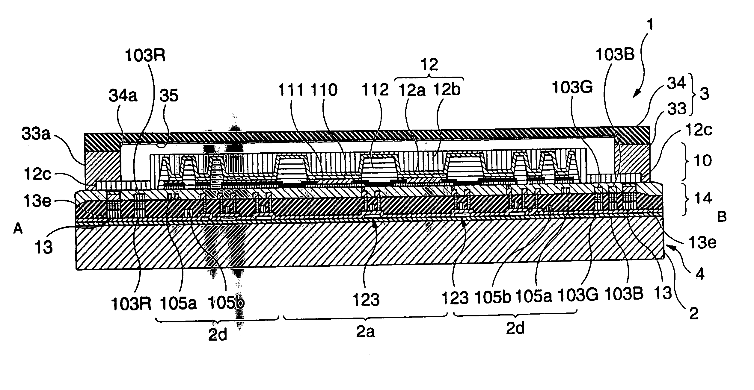
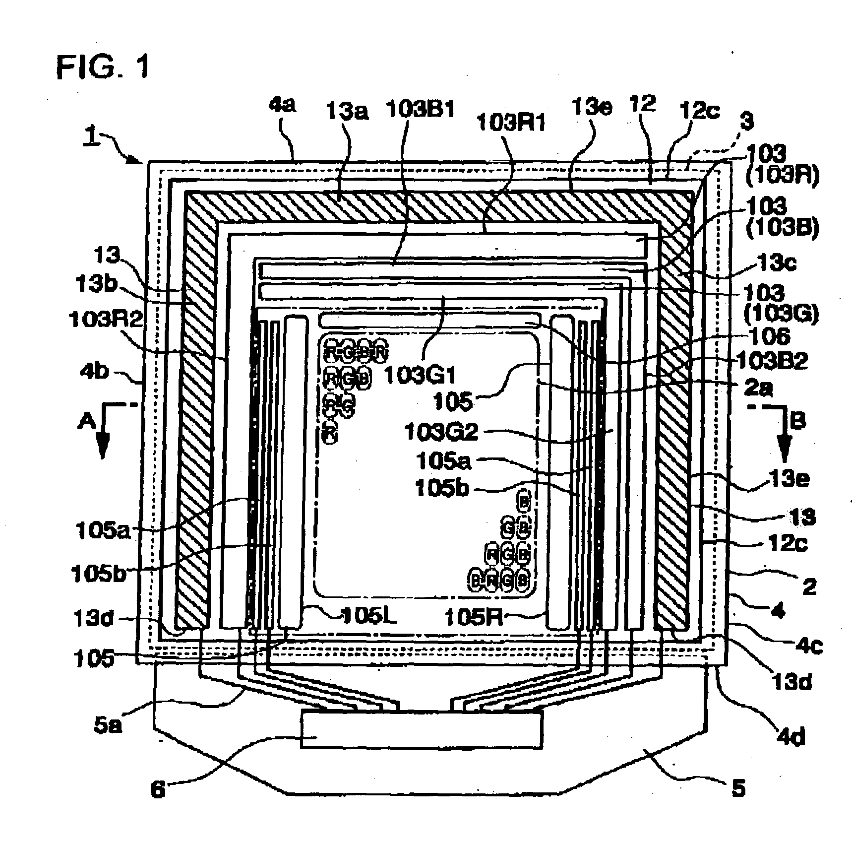
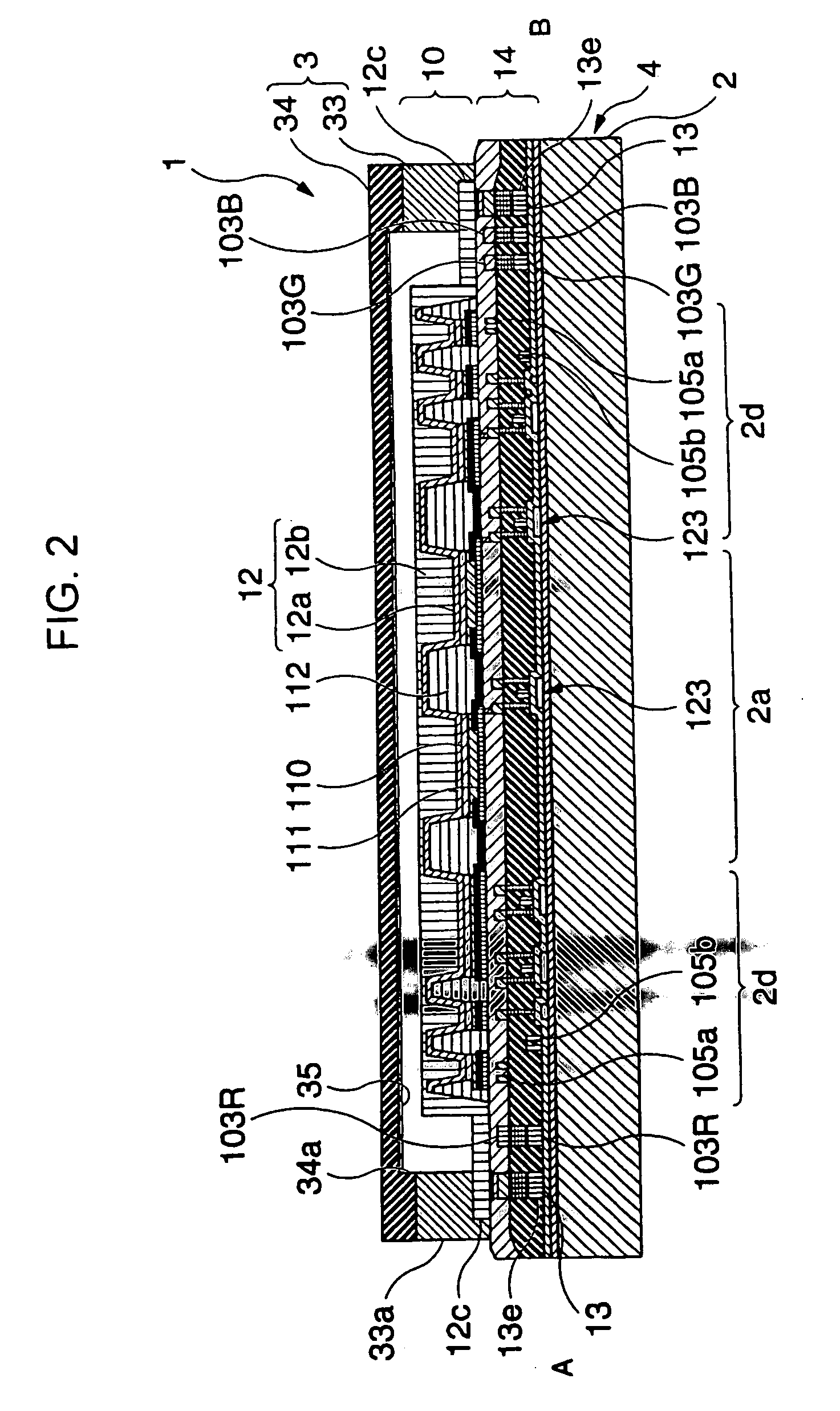
The invention provides a light-emitting device and an electronic apparatus, which are capable of preventing reduction of the amount of current flowing through light-emitting elements and which have an excellent display characteristic. Cathode wiring lines connected to a cathode are provided to surround an effective area outside the effective area where a plurality of pixels having light-emitting elements are provided. First to third power source lines connected to pixel electrodes are provided between the cathode wiring lines and the effective area.

Description

BACKGROUND OF THE INVENTION [0001] 1. Field of Invention [0002] The present invention relates to a light-emitting device and an electronic apparatus using the same. [0003] 2. Description of Related Art [0004] Related art organic electroluminescence (EL) display devices having light-emitting elements using an organic-light-emitting material between a substrate, in which pixel electrodes are formed, and a counter electrode, are disclosed in Gazette of Japanese Unexamined Patent Application Publication No. 5-3080. [0005] In the organic EL display devices, the light-emitting elements emit light by supplying current to the light-emitting elements. At that time, the brightness of the light-emitting element is determined by the amount of current basically supplied thereto. [0006] It is necessary to accurately set the amount of current to have a desired value because the brightness of such light-emitting elements is basically determined by the amount of supplied current. [0007] In order to ...

Claims


Application Information

Patent Timeline
Patent Type & Authority Applications(United States)
IPC IPC(8): H01J1/62H05B33/06G09G3/30H01L27/32H01L33/26H01L33/44H01L51/50H01L51/52H05B33/10H05B33/12H05B33/14H05B33/26
CPCH01L27/3211H01L27/3276Y10S428/917H01L51/5246H05B33/06H01L51/5221H10K59/35H10K59/131H10K59/8052H10K59/8722H10K50/8426H10K50/82
Inventor NAKANISHI, HAYATO
Owner INTELLECTUAL KEYSTONE TECH LLC
Learn More