
Slat structure for venetian blinds

a technology for venetian blinds and slats, which is applied in the direction of door/window protective devices, building components, constructions, etc., can solve the problems of increasing the total weight of the venetian blind, affecting the safety of the blind, and inconvenient transportation or assembly of the blind, so as to achieve convenient transportation, improve the heat dissipation effect, and reduce the weight

Inactive Publication Date: 2006-03-23
CHING FENG BLINDS INC CO LTD
View PDF4 Cites 14 Cited by
  • Summary
  • Abstract
  • Description
  • Claims
  • Application Information

AI Technical Summary

Benefits of technology

[0008] It is, therefore, the primary purpose of the present invention to provide a slat structure for Venetian blinds, including a Venetian blind made up of rope ladders suspended between an upper and lower beams for supporting a plurality of blind slats located in an equal space thereto wherein each blind slat is made in a hollow shape with a ventilation hole and a plurality of vertically-extending support guide ribs formed at the inner side thereof for better heat dissipation and insulation effects without the risk of getting hardened or deformed due to overheating by the sun so that the slats thereof can be neatly kept in good shape and evenly expanded in a smooth manner. Besides, the ventilation hole and the support guide ribs thereof are integrally molded in thin plates so as to make the Venetian blind lighter in weight for easier transportation and effortless assembly thereof.
[0009] It is, therefore, the second purpose of the present invention to provide a slat structure for Venetian blinds wherein the ventilation hole and the support guide ribs thereof are integrally made as a whole to facilitate a simpler and speedier processing thereof, economically reducing the cost in a standardized production and boosting the competitive power thereof on the market.
[0010] It is, therefore, the third purpose of the present invention to provide a slat structure for Venetian blinds wherein the slat with the ventilation hole and the support guide ribs integrally made in the processing thereof can maintain a smooth and neat surface without the sediment of dirt accumulated thereon and can avoid the disadvantage of a support plate getting loosened from the slat as shown in the second conventional blind slat structure so as to achieve the best using condition thereof.

Problems solved by technology

There are some drawbacks to such conventional blind slat structure.
First, the blind slat 14, made in a solid thick board, is provided with a certain weight, which can relatively increase the total weight of the Venetian blind 10 and makes the transportation or assembly thereof more difficult and inconvenient to be done.
Second, when the blind slats 14 of the Venetian blind 10, fully expanded to screen sunlight, are affected by the heat of sun, the hot air will totally concentrate on the blind slats 14 that, made in solid thick boards and unable to properly dissipate the heat thereof, not only tend to get hardened easily with a shortened lifetime thereof, but can increase the temperature indirectly and result in a stuffy and uncomfortable feeling indoors, failing to provide a heat insulation effect thereof.
Third, over long time of exposure to the glaring sunlight without proper dissipation of the heat thereof, the blind slats 14 of the Venetian blind 10 can easily get warped out of shape due to the overheating by the sun and are unable to be levelly expanded for sunscreen or privacy purpose thereof.
There are some disadvantages to the second blind slat structure.
First, the support plate 12′ is accommodated into the central through hole 11′ of each slat 10′ thereof, which, relatively increasing the total weight of the Venetian blind as a whole, tends to make the transportation and assembly of the Venetian blind thereof rather uneasy and inconvenient.
Second, the slat 10′ is sustained by the support plate 12′ adapted at the central through hole 11′ therein to provide a proper stiffness for use, and the support plate 12′ must be individually processed before mounted and fastened to the finished slat 10 thereof, which, complicated and time-consuming in the process, can increase the cost of material as well as production thereof.
In case of inaccurate attachment to the inner wall of the through hole 11′ thereof, the support plate 12′ tends to get loosened and protruded outside the through hole 11′ after the repeated raising or lowering of the slat 10′ thereof, destroying the total beauty of the Venetian blind as a whole and causing the inconvenience thereof in practical use.
However, the third conventional blind slat structure also includes some drawbacks.
First, the folded support ribs 12″, each stacked up into layers, are doubled up in thickness, which can increase the weight of the slat 10″ and make the transportation and assembly of the Venetian blind thereof rather uneasy and inconvenient.
Second, the central through hole 11″ of the slat 10″ is integrally and sequentially bent inwards from the outer side of one lateral sidewall thereof to form the folded support ribs 12″, which, rather complicated and tedious in the process thereof, can uneconomically increase the cost of production and inefficiently reduce the competitive power thereof.
Third, the folded support ribs 12″ of the slat 10″ are integrally bent inwards in a sequence with a plurality of the folding edges 121″ formed at the surface thereon, which not only destroys the neatness and the total beauty of the Venetian blind thereof, but tends to accumulate tiny dust or stones therein and results in the difficulty and inconvenience of cleaning thereof.

Method used


Image

  • Slat structure for venetian blinds
  • Slat structure for venetian blinds
  • Slat structure for venetian blinds

Examples


Embodiment Construction

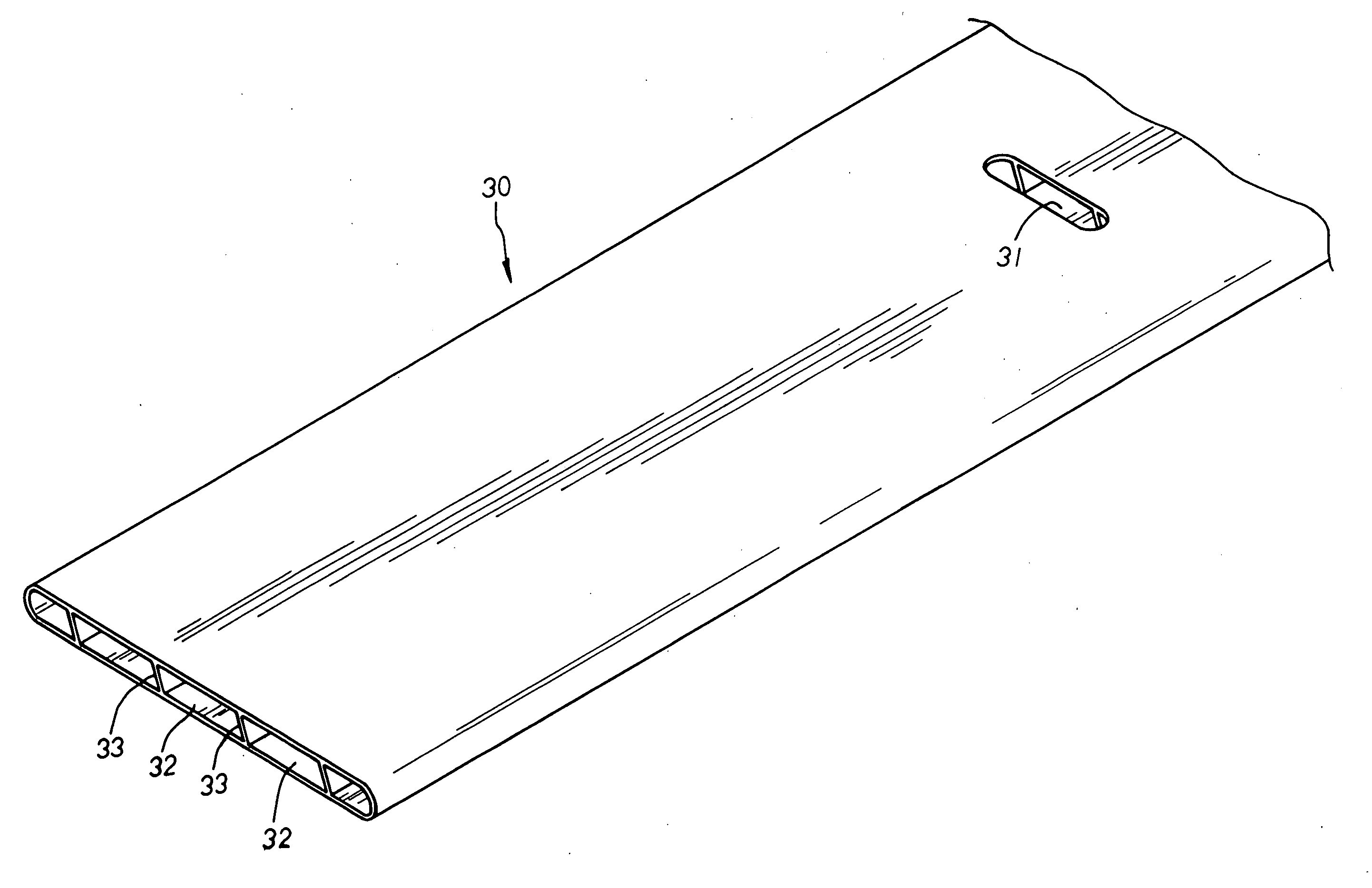
[0017] Please refer to FIGS. 5 to 6 inclusive. The present invention is related to a slat structure for Venetian blinds, including a Venetian blind 20 having rope ladders 23 suspended between an upper and lower beams 21, 22 for supporting a plurality of blind slats 30 located in an equal space thereto. A pull cord 24 is led through cord-passage holes 31 of each blind slat 30 thereof respectively, and the upper end of the pull cord 24 is wound around a pulley seat 211 mounted at one end of the upper beam 21 therein before hanging downwards there-from so as to control the lifting or expanding of the blind slats 30 thereby. Each blind slat 30 is made in a hollow shape and defined by a ventilation hole 32 disposed at the inner side thereof. A plurality of vertically-extending support guide ribs 33 is properly disposed at the ventilation hole 32 therein and integrally connected with the upper and lower inner walls of the ventilation hole 32 thereof so as to provide a reinforcing support ...


PUM


Abstract

A slat structure for Venetian blinds includes a Venetian blind made up of rope ladders suspended between an upper and lower beams for supporting a plurality of blind slats located in an equal space thereto, and a pull cord led through cord-passage holes of the blind slats thereof respectively before wound around a pulley seat mounted at one end of the upper beam to hang downwards there-from so as to raise or lower the blind slats thereby wherein each blind slat is made in a hollow shape with a ventilation hole formed at the inner side thereof for better heat dissipation and insulation effects thereby, and the ventilation hole thereof has a plurality of vertically-extending support guide ribs properly disposed therein and integrally connected with the upper and lower inner walls thereof so as to provide a reinforcing support effect thereby. The walls defining the ventilation hole and the support guide ribs thereof are made in thin plates, which makes the Venetian blind lighter in weight for easier transportation and effortless assembly thereof. Besides, the ventilation hole and the support guide ribs thereof are integrally made as a whole, facilitating a simpler and speedier processing thereof to reduce the cost of production for more competitive power on the market as well as maintaining a neat and smooth surface of the blind slats without the sediment of dirt accumulated thereto so as to achieve the best using condition thereof.

Description

BACKGROUND OF THE INVENTION [0001] The present invention is related to a slat structure for Venetian blinds, including a Venetian blind made up of rope ladders suspended between an upper and lower beams for supporting a plurality of blind slats located in an equal space thereto, and a pull cord wound around a pulley seat mounted at one end of the upper beam before hanging downwards there-from to raise or lower the blind slats thereby wherein each blind slat is made in a hollow shape with a ventilation hole and a plurality of vertically-extending support guide ribs properly disposed at the inner side thereof for better heat dissipation and insulation effects thereby. Besides, the walls defining the ventilation hole and the support guide ribs thereof are integrally molded in thin plates, which makes the Venetian blind lighter in weight for easier transportation and effortless assembly thereof, and facilitates a simpler and speedier processing thereof to reduce the cost of production a...

Claims


Application Information

Patent Timeline
Patent Type & Authority Applications(United States)
IPC IPC(8): E06B3/12E06B9/26E06B9/386
CPCE06B9/386
Inventor HSU, BEN
Owner CHING FENG BLINDS INC CO LTD
Learn More