Ultrasound system power management

a technology of ultrasonic systems and power management, applied in the field of ultrasonic system power conservation, can solve the problems of acoustic signal dead time between acoustic signal frames being often greater than acoustic signal dead time, and achieve the effect of minimizing the tim

Active Publication Date: 2006-03-16
FUJIFILM SONOSITE
View PDF7 Cites 31 Cited by
  • Summary
  • Abstract
  • Description
  • Claims
  • Application Information

AI Technical Summary

Benefits of technology

[0005] The present invention is directed to systems and methods which power-down (reduce power to or deactivate) circuits in an acoustic signal path during periods in which an acoustic signal is not being acquired by a portable ultrasonic diagnostic system, although image processing and other system functions may be continued normally. According to preferred embodiments, acoustic signal path circuits are powered-down between each of a series of acoustic signal acquire operations, such as between acoustic signal scan lines, between groups of scan lines, and / or between acoustic signal scan frames. By applying appropriate timing techniques, such acoustic signal path circuits may be again powered-up just prior to acoustic signal acquire operations, such as to transmit an acoustic pulse and / or receive a return echo, thereby minimizing the time such circuits are energized without otherwise affecting the operation of the portable ultrasonic diagnostic system.

Problems solved by technology

For example, it is expected that the acoustic signal dead time between acoustic signal frames will often be greater than the acoustic signal dead time between acoustic signal lines due to the increased processing burden associated with forming and displaying the resulting image.

Method used


Image

  • Ultrasound system power management
  • Ultrasound system power management

Examples


Embodiment Construction

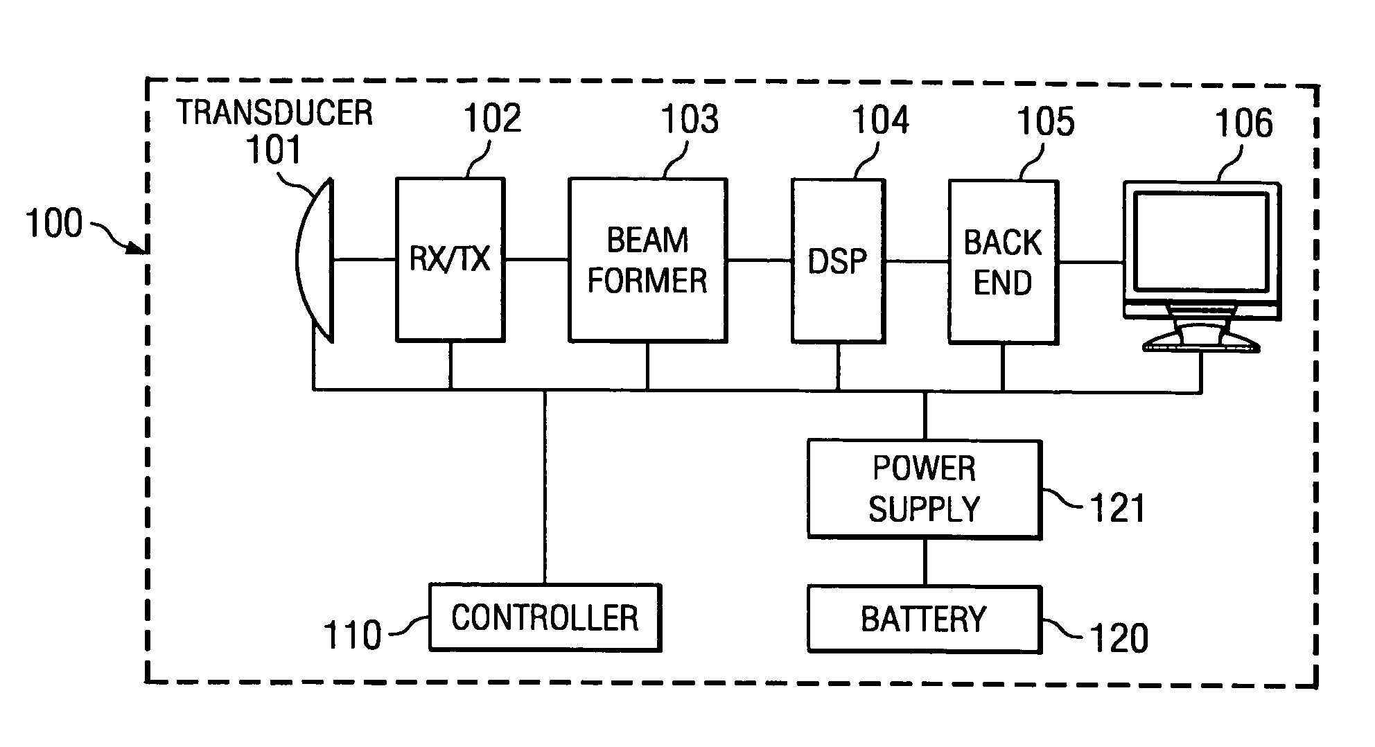
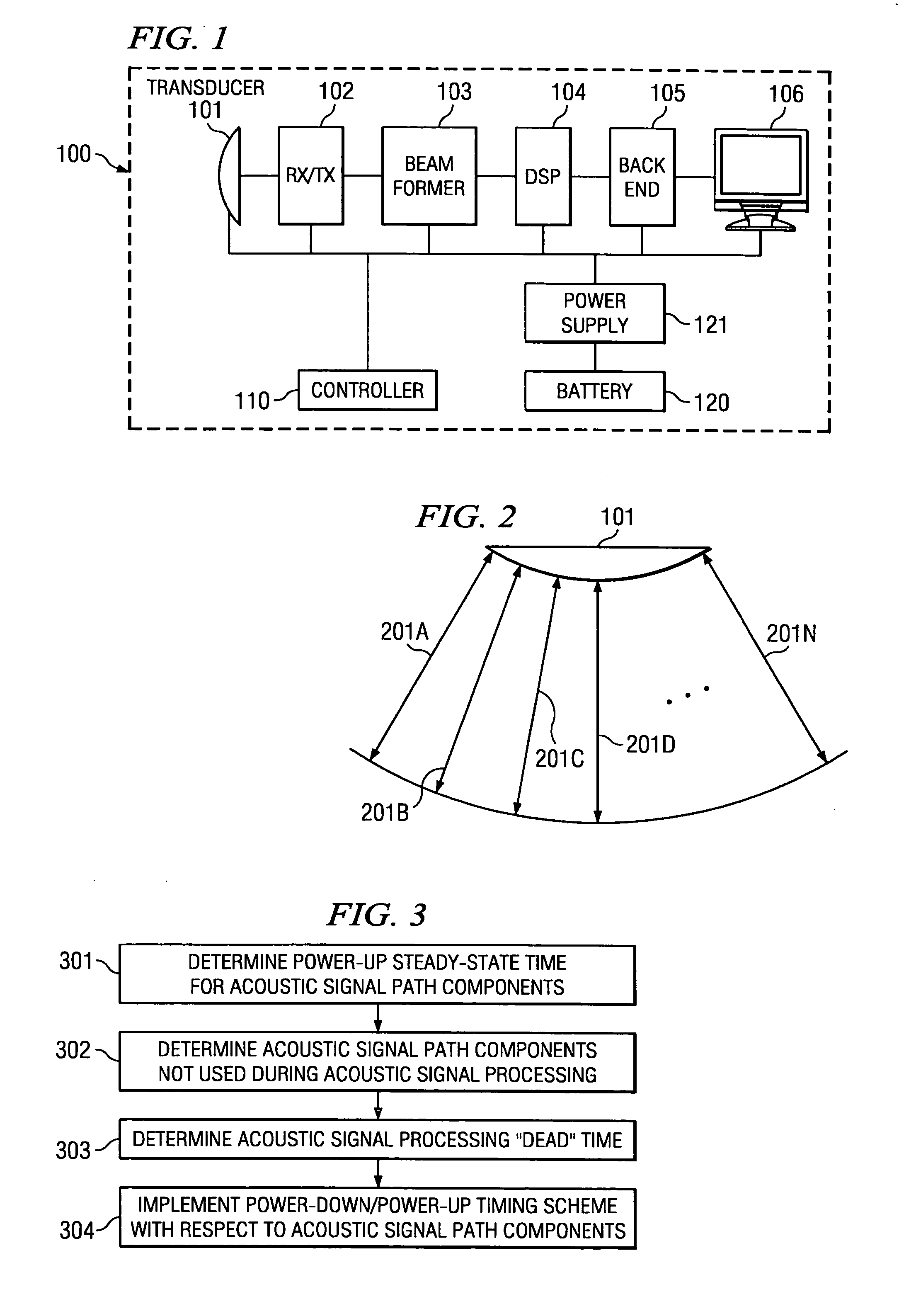
[0017] Directing attention to FIG. 1, a high level block diagram of an ultrasonic diagnostic system adapted according to an embodiment of the present invention is shown as system 100. System 100 displays signals captured by transducer 101 (e.g., an array transducer) as images on monitor 106 (e.g., a cathode ray tube (CRT), liquid crystal display (LCD), gas plasma display, etcetera). The illustrated embodiment of system 100 includes 4 functional blocks, such as may comprise application specific integrated circuits (ASICs) between transducer 101 and monitor 106. Specifically, the embodiment of FIG. 1 includes transmit / receive module 102 which is connected to the elements of transducer 101, beamformer module 103 which may perform and control transmit and receive beamforming, digital signal processing (DSP) module 104 which may provide processing of the ultrasound signals such as filtering, and back end module 105 which may receive processed ultrasound signals and produce ultrasound ima...


PUM


Abstract

Disclosed are systems and methods which power-down (reduce power to or deactivate) circuits in an ultrasound system during periods in which an acoustic signal is not being acquired, although image processing and other system functions are continued normally. Such circuits may be powered-down between each of a series of acoustic signal acquire operations, such as between acoustic signal scan lines and/or between acoustic signal scan frames. The circuitry which is powered-down between scan lines and scan frames may not the same, although some circuitry may be common to both. Embodiments may further operate to adjust the acoustic signal dead time circuitry power-down cycle, such as by adjusting acoustic signal frame rates. Power-down techniques may be utilized in addressing power issues and/or in controlling thermal aspects of the operation of an ultrasound diagnostic system.

Description

CROSS-REFERENCE TO RELATED APPLICATIONS [0001] The present application is related to co-pending and commonly assigned United States Patent Application Attorney Docket No. 65744 / P015US / 10314373, entitled “ULTRASONIC TRANSDUCER HAVING A THIN WIRE INTERFACE,” filed concurrently herewith and U.S. patent application Ser. No. 10 / 847,643, filed May 17, 2004, entitled “PROCESSING OF MEDICAL SIGNALS,” the disclosure of which is hereby incorporated herein by reference.TECHNICAL FIELD [0002] The invention is related to techniques for conserving power and, more particularly, to ultrasound system power conservation. BACKGROUND OF THE INVENTION [0003] In recent years advancements have been made in moving away from the well known large cart based ultrasonic diagnostic systems. Although complex cart based ultrasonic instruments generally provide excellent image quality and a number of features, such as B mode, color Doppler imaging, three-dimensional display, etcetera, the systems are typically ver...

Claims


Application Information

Patent Timeline
Patent Type & Authority Applications(United States)
IPC IPC(8): A61B8/00
CPCA61B8/00A61B2560/0209Y10S128/916G01S15/899A61B8/56G01S7/52096
Inventor LITTLE, BLAKE W.
Owner FUJIFILM SONOSITE
Why Eureka
Try Eureka