
Aligned and open-ended nanotube structure and method for making the same

a technology of nanotubes and nanotube cores, which is applied in the manufacture of cell components, electric discharge tubes/lamps, electrode systems, etc., can solve the problems of reducing the performance of electron field emitter designs, reducing the applied field, and reducing the cost of manufacturing

Inactive Publication Date: 2006-03-16
SAMSUNG ELECTRONICS CO LTD +1
View PDF8 Cites 85 Cited by
  • Summary
  • Abstract
  • Description
  • Claims
  • Application Information

AI Technical Summary

Benefits of technology

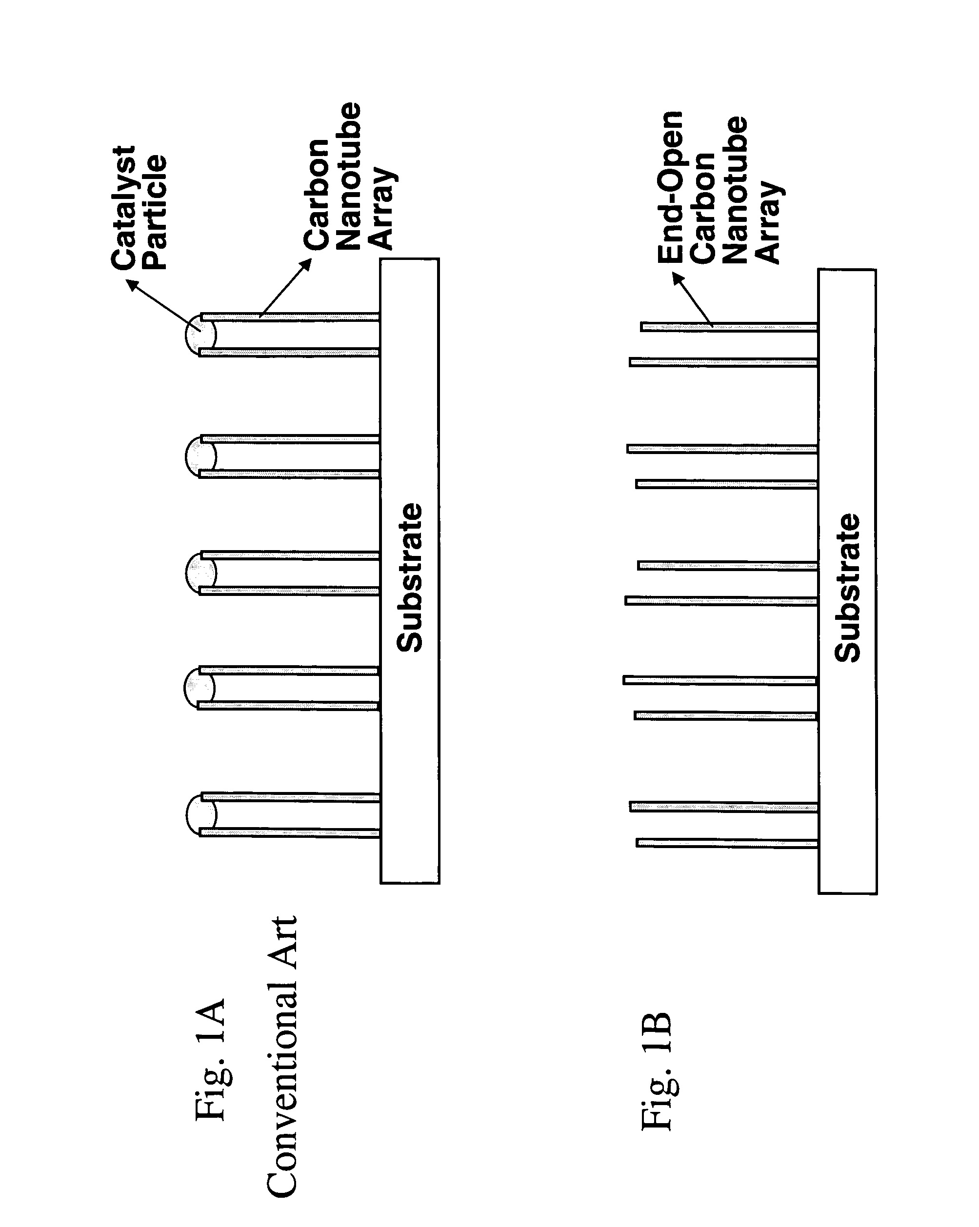
[0036] In example embodiments of the present invention, carbon nanotubes (CNTs) may be grown in the form of well aligned, vertically oriented fibers on a substrate, either as a dense forest or as a patterned, spaced-apart array. Such a vertically aligned and straight nanotube geometry is useful for improved performance of electron field emitter designs.
[0037] If the normally capped top ends of carbon nanotubes geometrically aligned and fixed on a flat substrate can be made open, several advantages may result according to example embodiments of the present invention, for example, the field concentration at the open-end tip of the CNTs may be higher thus allowing electron field emission at a lower applied field than conventional capped nanotubes. Other advantages of example embodiments of the present invention include ease of fabricating nano-composite materials and structures by filling the now-accessible nanotube core with other materials, ease of fabricating and using such an open-ended nanotube array as a nano-needle delivery device for therapeutic drugs, biological, molecules such as DNA for gene therapy, enzymes and proteins to influence cell behavior in animals, humans or plants, nano-scale delivery of chemical reactants such as catalysts, etc.

Problems solved by technology

Because of the catalyst particles, the nanotube core may not be accessible for additional fabrication, for example, core filling.
Heating CNTs in the presence of air for short durations at temperatures at about 700° C. may result in the burning away of the tube caps and / or the thinning of tube walls.
However, opening all of the tubes may require oxidizing the majority of the CNTs.
However, CNTs opened via these methods may be of disparate lengths, may have their vertical alignment configuration disrupted, e.g., by their bundling during wet processing, and / or may have their walls damaged and / or their surfaces functionalized by strong acids.

Method used


Image

  • Aligned and open-ended nanotube structure and method for making the same
  • Aligned and open-ended nanotube structure and method for making the same
  • Aligned and open-ended nanotube structure and method for making the same

Examples


Embodiment Construction

[0058] Detailed illustrative embodiments of the present invention are disclosed herein. However, specific structural and functional details disclosed herein are merely representative for purposes of describing example embodiments of the present invention. This invention may, however, may be embodied in many alternate forms and should not be construed as limited to only the embodiments set forth herein.

[0059] Accordingly, while example embodiments of the invention are capable of various modifications and alternative forms, embodiments thereof are shown by way of example in the drawings and will herein be described in detail. It should be understood, however, that there is no intent to limit example embodiments of the invention to the particular forms disclosed, but on the contrary, example embodiments of the invention are to cover all modifications, equivalents, and alternatives falling within the scope of the invention. Like numbers refer to like elements throughout the description...


PUM

PropertyMeasurementUnit
Lengthaaaaaaaaaa
Lengthaaaaaaaaaa
Lengthaaaaaaaaaa

Abstract

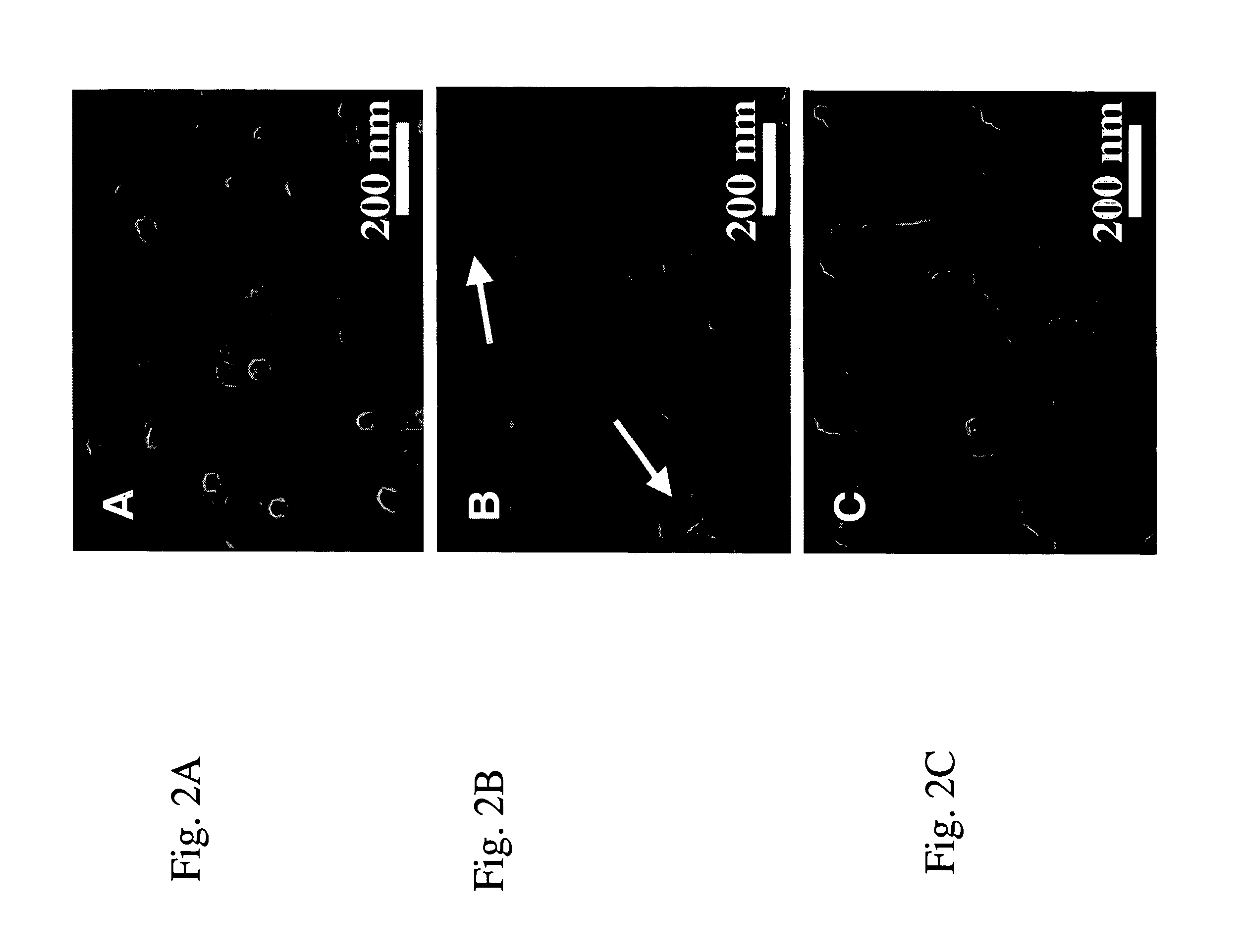
Aligned and open-ended nanotube structures, methods for making the same, and devices including open-ended nanotubes. An aligned and open-ended nanotube structure which is free of catalyst particles at top ends, the aligned and open-ended nanotube structure having an uneven open-end height with local protruding portions. A method of opening an end of a nanotube including a catalyst particle including sputter etching the nanotube to remove an amorphous layer, bend the nanotube to one side, open a hole in the nanotube, and cause detachment of the catalyst particle.

Description

PRIORITY STATEMENT [0001] This application claims the benefit of U.S. Provisional Patent Application No. 60 / 608,641, filed on Sep. 10, 2004, in the U.S. Patent and Trademark Office, the disclosure of which is incorporated herein in its entirety by reference.BACKGROUND OF THE INVENTION [0002] 1. Field of the Invention [0003] Example embodiments of the present invention relate to aligned and open-ended nanotube structures, methods for making the same, and devices including open-ended nanotubes, for example, carbon nanotubes with vertically aligned structure and devices including open-ended nanotubes with vertically aligned structure. [0004] 2. Description of the Related Art [0005] Carbon nanotubes (CNTs) have been studied for many different applications due to their electrical and / or mechanical properties. Carbon nanotubes have already been shown to be useful for a variety of applications, for example, field emission devices, nanoscale electromechanical actuators, field-effect transis...

Claims


Application Information

Patent Timeline
IPC IPC(8): C23C14/00B32B9/00
CPCB82B3/00Y10T428/30B82Y40/00C01B3/0021C01B31/0286C01B2202/08H01J1/304H01J9/025H01J17/49H01J31/127H01J2201/30453H01J2329/0455H01M4/90H01M4/9083H01M4/92H01M4/926Y02E60/325Y02E60/50B82Y30/00C01B32/178Y02E60/32
Inventor JIN, SUNGHOKIM, DONG-WOOKYOO, IN KYUNG
Owner SAMSUNG ELECTRONICS CO LTD
Learn More