
Phosphor sheet for radiation detector, radiation detector employment it and equipment for detecting radiation

a radiation detector and phosphor sheet technology, applied in the direction of optical radiation measurement, fluorescence/phosphorescence, instruments, etc., can solve the problems of insufficient enhancement of the sensitivity of the x-ray detector including photoelectric conversion films, and the size of the apparatus

Active Publication Date: 2006-03-16
KK TOSHIBA
View PDF12 Cites 22 Cited by
  • Summary
  • Abstract
  • Description
  • Claims
  • Application Information

AI Technical Summary

Benefits of technology

[0012] A second phosphor sheet for a radiation detector of the present invention is a phosphor sheet provided to be attached to a photoelectric conversion film of the radiation detector, and is characterized by comprising a support having a sheet shape, and a phosphor layer which is pro...

Problems solved by technology

Therefore, an I. I. tube causes the problem of increasing the size of apparatus.
However, the phosphor sheets using the conventional Gd2O2S: Pr phosphor, the Gd2O2S: Tb phosphor and the like have the problem of being incapable of sufficiently enhancing sensitivity of the X-ray detectors including photoelectric conversion films.

Method used


Image

  • Phosphor sheet for radiation detector, radiation detector employment it and equipment for detecting radiation
  • Phosphor sheet for radiation detector, radiation detector employment it and equipment for detecting radiation
  • Phosphor sheet for radiation detector, radiation detector employment it and equipment for detecting radiation

Examples


example 1

[0079] The Gd2O2S: Eu phosphor (Eu concentration 0.5 mol %) of the average particle size of 8 μm was prepared. 1 part by weight of polyvinyl butyral resin as a binder and a proper amount of ethyl acetate as an organic solvent were mixed into 10 parts by weight of Gd2O2S: Eu phosphor powder, and thereby, the phosphor coating solution was prepared. This phosphor coating solution was uniformly coated on the sheet base material constituted of the white polyethylene terephthalate film (containing titanium dioxide) of 400 mm long, 300 mm broad and 250 μm thick by the knife coater so that the coating mass of the phosphor becomes 900 g / m2 (90 mg / cm2) and the coating film thickness becomes about 200 μm, and dried, and thereby, the phosphor layer was formed. The phosphor sheet thus obtained was submitted to the characteristic evaluation which will be described later.

example 2

[0080] The phosphor sheet was produced as in Example 1 except that the Lu2O2S: Eu phosphor of the Eu concentration of 0.5 mol % was used instead of the phosphor in example 1. The phosphor sheet using this Lu2O2S: Eu phosphor was submitted to the characteristic evaluation which will be described later.

examples 3 and 4

[0084] The phosphor sheets were produced similarly to Example 1 except that the Gd2O2S: Eu phosphor of the Eu concentration of 0.01 mol % (example 3) and the Gd2O2S: Eu phosphor of the Eu concentration of 3.5 mol % (example 4) were used instead of the phosphor in example 1. The sensitivity and the definition of these phosphor sheets were measured similarly to Example 1. The results are shown in Table 2. The sensitivities and definitions in Table 2 are the relative values when the measurement result of Comparative Example 1 is set as 100.


PUM

PropertyMeasurementUnit
Fractionaaaaaaaaaa
Fractionaaaaaaaaaa
Particle sizeaaaaaaaaaa

Abstract

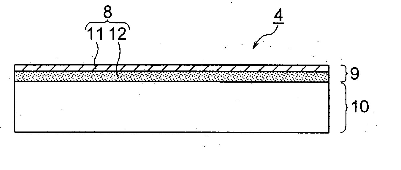
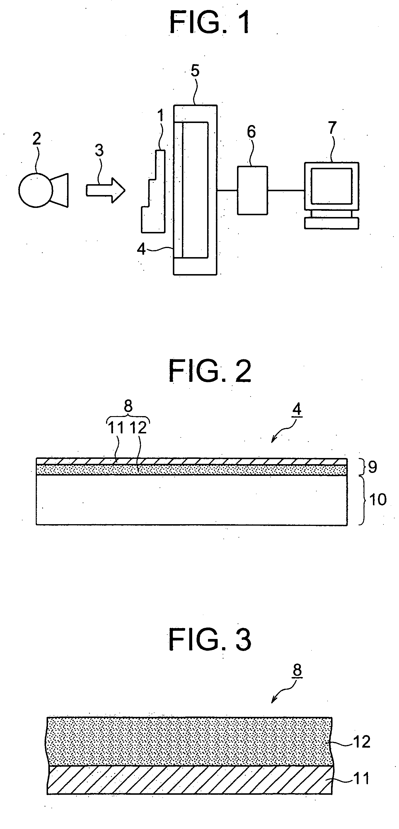
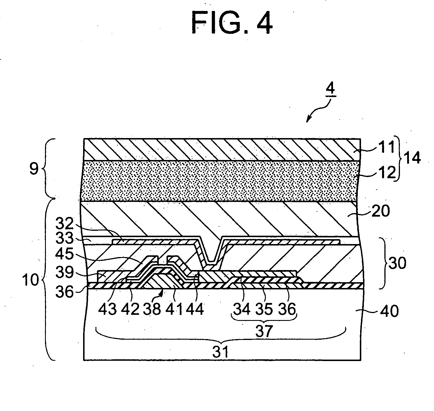
A phosphor sheet 8 for a radiation detector used by being attached to a photoelectric conversion film 20 of a radiation detector 4 includes a sheet-shaped support 11, and a phosphor layer 12 provided thereon. The phosphor layer 12 contains a europium-activated rare earth oxysulfide phosphor having a europium concentration in a range of 0.01 to 3.5 mol %. The radiation detector 4 includes the phosphor sheet 8 being irradiated with radiation rays transmitted through a specimen and converting the radiation rays into light, a photoelectric conversion film 20 for converting the light from the phosphor sheet 8 into electric charges, and a charge information reading section 30 for reading out the charges generated on the photoelectric conversion film 20 for each of a plurality of pixels 31.

Description

TECHNICAL FIELD [0001] The present invention relates to a phosphor sheet for a radiation detector used for medical diagnosis, various kinds of non-destructive examination and the like, and an indirect conversion type radiation detector employing it and an apparatus for radiographic examination. BACKGROUND ART [0002] Radiography is utilized for medical diagnosis, industrial non-destructive examination and the like. An intensifying screen / film method is generally applied to radiography. The intensifying screen / film method is a method for obtaining an X-ray image by converting x-rays transmitted through a specimen into visible light by an intensifying screen, and photosensitizing a film by this visible light. Medical diagnosis, non-destructive examination and the like are carried out based on the X-ray images formed on the films. [0003] Meanwhile, a method for performing examination by converting an X-ray image into an electric signal and performing image processing for this electric s...

Claims


Application Information

Patent Timeline
IPC IPC(8): G01T1/20H05B33/00C09K11/77
CPCC09K11/7767G21K4/00C09K11/7784
Inventor OYAIZU, EIJIOKAMURA, MASAMI
Owner KK TOSHIBA
Learn More