
Visual vector display generation of very fast moving elements

Inactive Publication Date: 2006-03-09
RAST RODGER H +1
View PDF0 Cites 93 Cited by
  • Summary
  • Abstract
  • Description
  • Claims
  • Application Information

AI Technical Summary

Benefits of technology

[0014] The advantages of this system should be readily recognized. Combatants can better find cover when under fire, as both the path and origination of bullets can be quickly seen. The historical paths can also be seen wherein the user can determine the movements of the enemy. The benefits for returning fire are even more significant, in that the user only need follow a single vector or recognize where multiple vectors converge to detect an enemy position. The enemy can be fired upon without the need of seeing them physically, but in response to the fire pattern.
[0024] Another aspect of the invention is to provide (at least on higher quality systems) the ability to generate and display vectors in their proper 3D position even if the user point of view or position changes.
[0035] Another aspect of the invention is to provide a fail safe which prevents the improper projectile from being activated.
[0036] Another aspect of the invention is to provide a multi-round cartridge which may be readily replaced into the weapon platform.
[0037] Another aspect of the invention is to provide a small arms device that is highly reliable, very light weight, and expendable.

Problems solved by technology

However, one can never be sure the path of the incoming rounds, wherein taking cover and returning fire properly is an “art”.
As a result our military is left to rely on their perceptions of the situation and both combat effectiveness and safety are compromised.
However, when a combatant is under cover it is often difficult to safely gather information from nearby locations.
However, including conventional weapons systems into these platforms is often problematic, or at best inefficient, as the technologies do not scale well to small platforms as the mechanisms for round storage, loading, firing, and shell ejection require heavy and expensive mechanisms.

Method used


Image

  • Visual vector display generation of very fast moving elements
  • Visual vector display generation of very fast moving elements
  • Visual vector display generation of very fast moving elements

Examples


Embodiment Construction

)

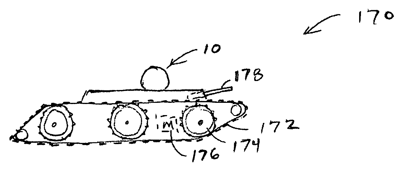
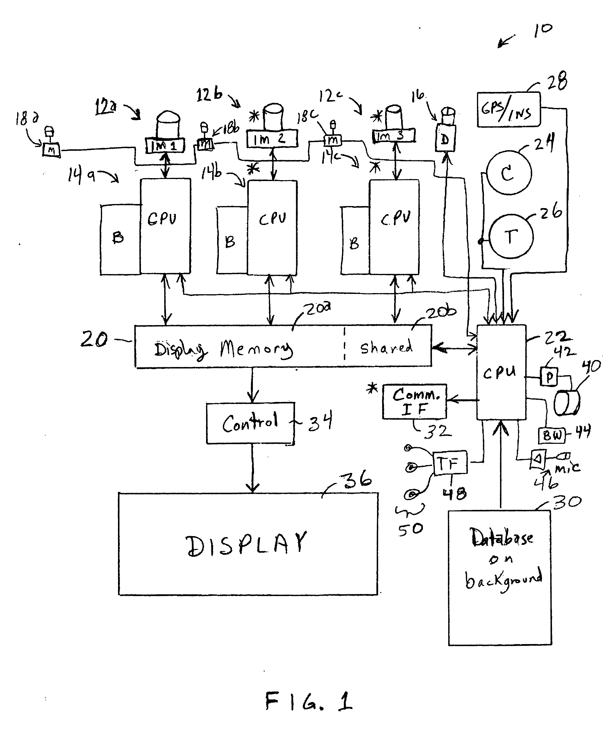
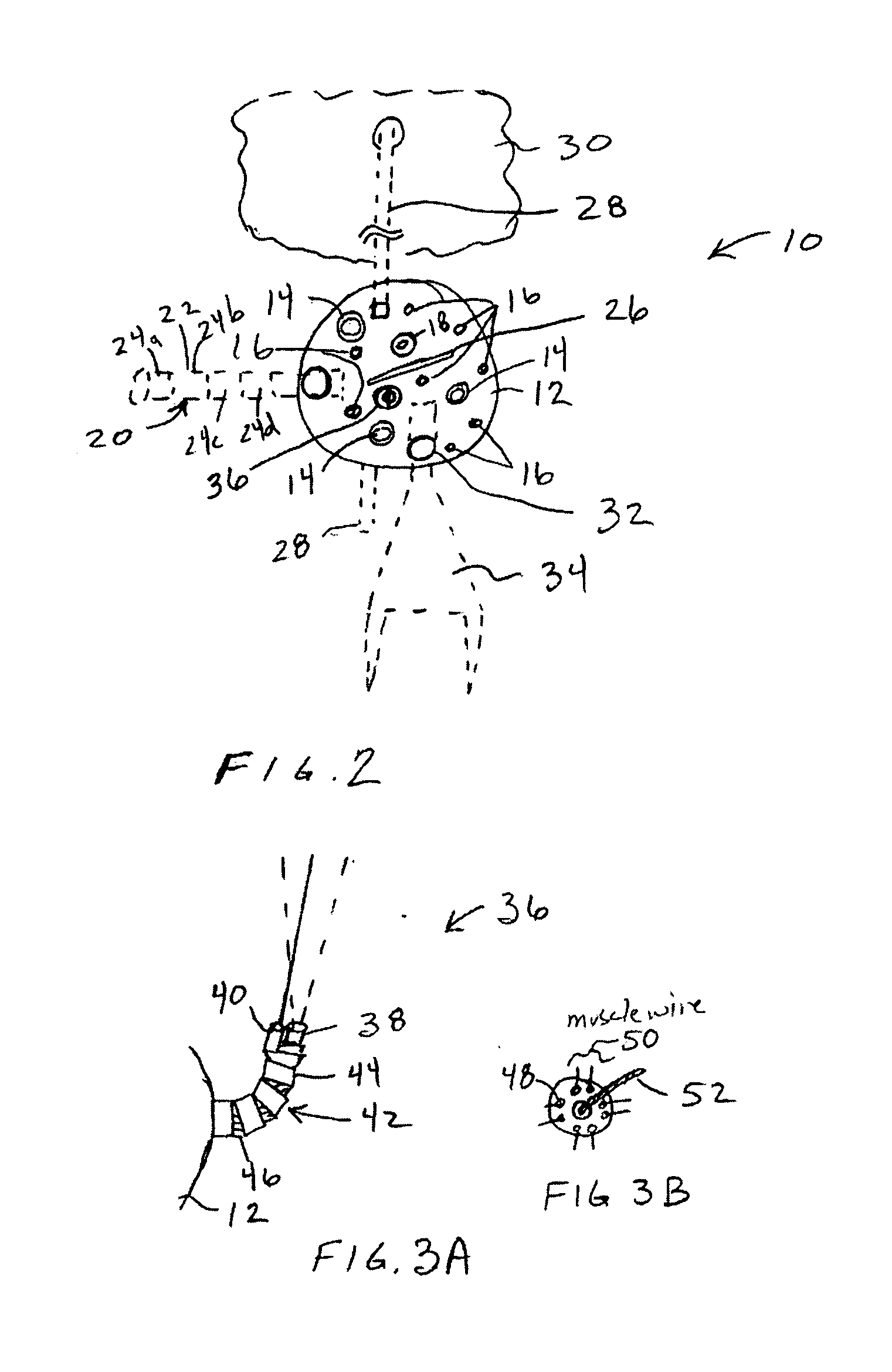
[0072] Referring more specifically to the drawings for illustrative purposes, the present invention is embodied in the method generally described in FIG. 1 to FIG. 40. The following description is presented to enable one of ordinary skill in the art to make and use the invention as provided in the context of a particular application and its requirements. Unnecessary technical details, which extend beyond the necessary information allowing a person of ordinary skill in the art to practice the invention, are preferably absent for the sake of clarity and brevity. Furthermore, it is to be understood that inventive aspects may be practiced in numerous alternative ways by one or ordinary skill without departing from the teachings of the invention. Therefore, various modifications to the preferred embodiments will be readily apparent to those skilled in the art, and the principles defined here may be applied to other embodiments. Thus the present invention is not intended to be limited to...


PUM


Abstract

Apparatus, system and method for providiing tactical information. One aspect is a system and method for displaying vectors (preferably in real time) for very fast moving (VFM) elements, such as projectiles (e.g., bullets or shells), missiles, and other transient events that arise in a battlefield or civil police action. The system optically and / or acoustically collects information about the ordinance and displays vectors of otherwise unseen ordinance. One aspect is a device for collecting intelligence on and confusing enemy troops, as well as small munition deployment.

Description

CROSS-REFERENCE TO RELATED APPLICATIONS [0001] This application claims priority from provisional patent application Ser. No. 60 / 608,789 filed Sep. 9, 2004 which is incorporated herein by reference and priority to which is claimed. [0002] This application is related to these copending applications, which are subject to a common assignment: Utility patent application Ser. No. 10 / 612,221 filed Jul. 1, 2003; Provisional patent application Ser. No. 60 / 394,160 filed Jul. 1, 2002; Utility patent application docket number KeyboardRAST070103 Ser. No. 10 / 612,777 as filed Jul. 1, 2003; Provisional patent application describing an “Eceptor within docket “PPA_RAST061403” Ser. No. 60 / 478,900 as filed Jun. 14, 2003; Provisional patent application docket “PPA_RAST120103” Ser. No. 60 / 526,376 filed Dec. 1, 2003; Utility patent application docket “Display_RAST092303” Ser. No. 10 / 670,432 filed Sep. 23, 2003; Provisional patent application Ser. No. 60 / 413,199 filed Sep. 23, 2002; Utility patent applicat...

Claims


Application Information

Patent Timeline
IPC IPC(8): G06K9/00
CPCF41G3/147G01S5/16G01S3/784F42B5/035
Inventor RAST, RODGER H.WIESNER, RICK MARTIN
Owner RAST RODGER H
Learn More