
Goggles

Active Publication Date: 2010-09-16
SWANS
View PDF30 Cites 12 Cited by
  • Summary
  • Abstract
  • Description
  • Claims
  • Application Information

AI Technical Summary

Benefits of technology

[0028]Since the goggles of the present invention is constituted as stated above, the lens of the goggles can be readily replaced with a lens having optimum visibility performance according to changes in natural environment due to the intensity of the sun, snowfall or rainfall.
[0029]Further, in the goggles of the present invention, the lens can be prevented from being touched by a wearer's hands in replacement, and thus even a wearer has gloves on, the gloves are unlikely to touch the lens and the lens can be prevented from being rubbed and scratched.
[0030]In the goggles of the present invention, the lock mechanism is prevented from malfunctions, thereby reducing the possibility of unwanted removal of the lens from the frame.
[0031]Further, the goggles of the present invention are, of course, also suitable for use for sports that do not require a helmet. Thus the goggles are suitable for sports both requiring a helmet and not requiring it and the versatility is enhanced.
[0032]The goggles of the present invention have high shock absorbing properties, thereby preventing the frame and / or the lens from breaking, and a wearer from being injured.

Problems solved by technology

However, for a wearer who has gloves on and could use his or her thumbs and fingers less freely, it is difficult to engage them and it takes time to replace the single lens 32.
However, the fitting groove 55 formed in the inner surface of the lens holding frame 51 fits and holds the lens 54 so as to prevent the lens 54 from accidental removal but replacement of lenses is not possible in the goggles.
Thus, the lens cannot be replaced with a lens having optimum visibility performance according to changes in the natural environment due to the intensity of the sun, snowfall or rainfall.

Method used


Image

  • Goggles
  • Goggles
  • Goggles

Examples


Embodiment Construction

[0058]Embodiments of goggles of the present invention will be described below in detail with reference to the drawings.

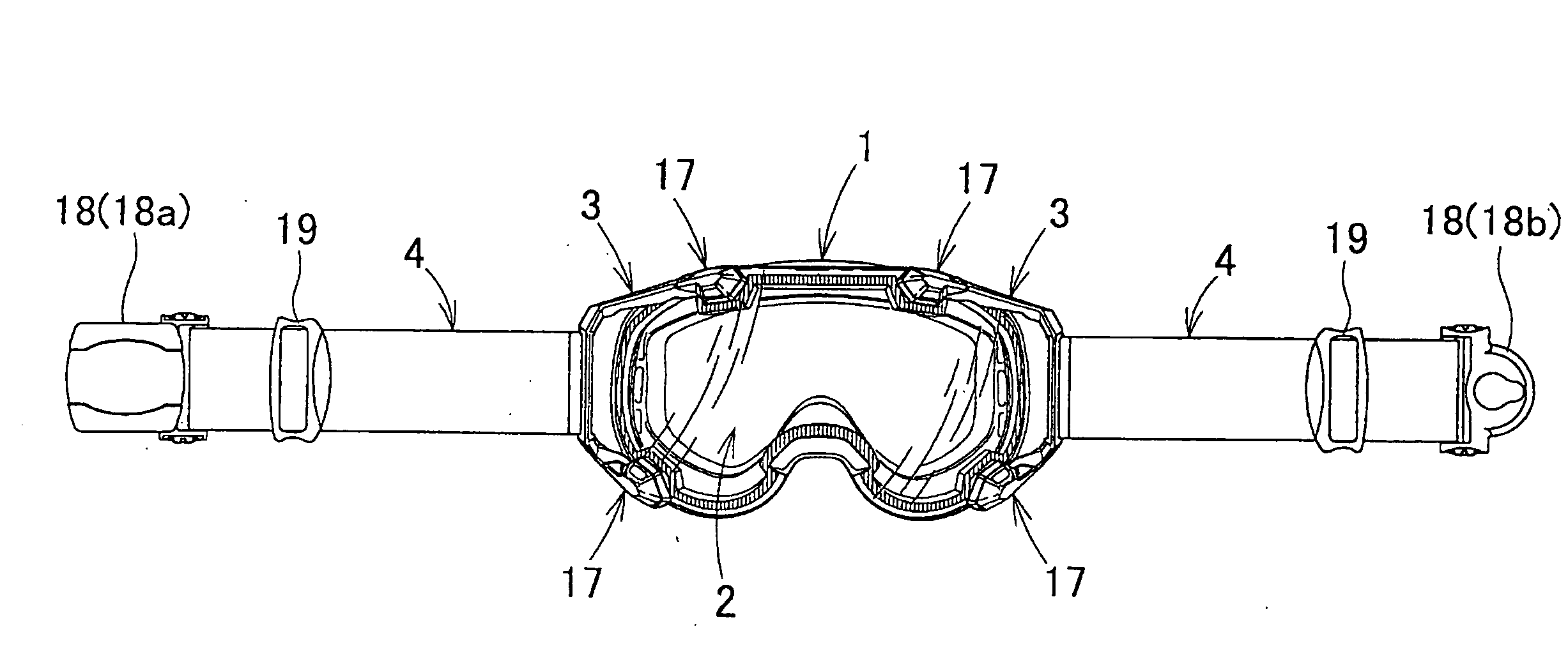
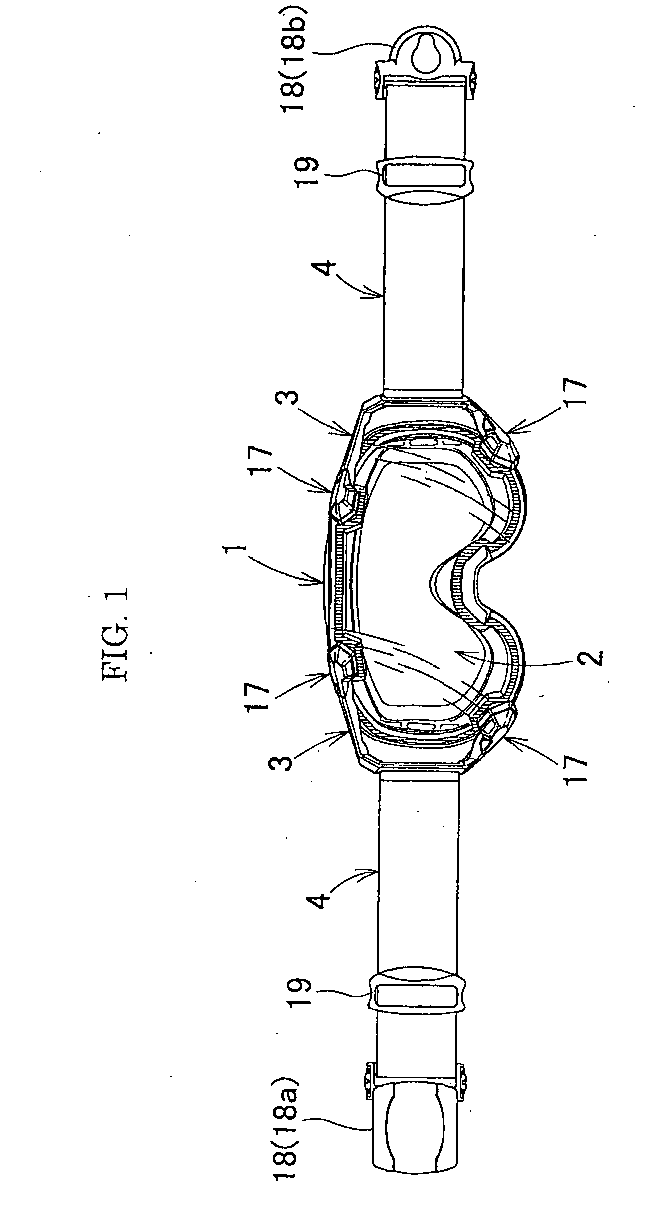
[0059]The goggles of the present invention include a frame 1, a lens 2, a pair of belt arms 3 and a pair of fitting belts4, as main structural members.

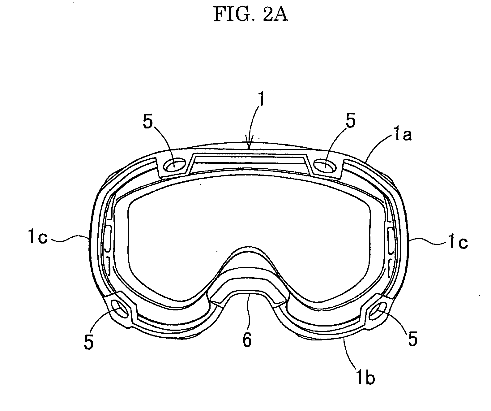
[0060]The frame 1 is generally made of flexible soft elastic synthetic resin or the like. The frame 1 has stop holes 5 (first stop holes) in four positions: left and right positions of upper and lower frames in a periphery of a surface of the frame in contact with the lens 2. More specifically, as shown in FIG. 2A, one stop hole 5 is provided each left and right of a middle of both of a horizontally elongated upper frame 1a and a horizontally elongated lower frame 1b of the frame 1. Further, the lower side of the frame (i.e. the lower frame 1b) has a nose pad portion 6 formed by recessing the middle portion. A groove 7a is provided inside the nose pad portion 6, and a pawl 8a is provided in the groove 7a (see FIG. 5A)...


PUM


Abstract

Goggles include a frame, a lens and a pair of left and right belt arms. On the frame a first stop hole is provided each left and right of a middle of each of an upper frame and a lower frame of the frame. The lens has an upper side and a lower side each of which is provided with a second stop hole at a position corresponding to each first stop hole in the frame. Each of the pair of left and right belt arms has bifurcated portions, and each end of the bifurcated portions is provided with a lock mechanism. The frame and the lens are placed on each other and the respective first and second stop holes are aligned. By the mechanisms of the belt arms, the first and second stop holes are brought into either a lock state to secure the frame, the lens and the pair of left and right belt arms, or an unlock state where the lock state is released to separate them.

Description

CROSS REFERENCE TO RELATED APPLICATIONS[0001]This application claims priority of Japanese Application No. 2009-61422 filed on Mar. 13, 2009, the entire contents of which are hereby incorporated herein by reference.BACKGROUND OF THE INVENTION[0002]1. Field of the Invention[0003]The present invention relates to goggles applicable to snow goggles used for skiing, snowboarding or snow shoveling, motor sport goggles for riding bikes or buggies, water sport goggles for canoeing yachting, or surfing, or dustproof goggles used in factories or the like, and more particularly to goggles, as sport goggles, suitably used for doing sports that require a helmet.[0004]2. Description of the Related Art[0005]Conventional goggles include, for example, a single lens 32 removably mounted to a frame body 31 as shown in FIG. 12. In the goggles, the frame body 31 has a lens fitting peripheral potion, each of upper and lower portions thereof has an engaging protrusion 35 that engages an engaging portion 34...

Claims


Application Information

Patent Timeline
IPC IPC(8): A61F9/02
CPCA61F9/027A61F9/025A63B33/002
Inventor TOMINAGA, HIROFUMIHADEHARA, SHINICHI
Owner SWANS
Learn More