
Steering device

a steering device and v-letter technology, applied in the direction of electric steering, power steering, vehicle components, etc., can solve the problem that the attendant wire of the v-letter shape in the prior art steering device no longer arises

Active Publication Date: 2006-03-09
JTEKT CORP +1
View PDF11 Cites 5 Cited by
  • Summary
  • Abstract
  • Description
  • Claims
  • Application Information

AI Technical Summary

Benefits of technology

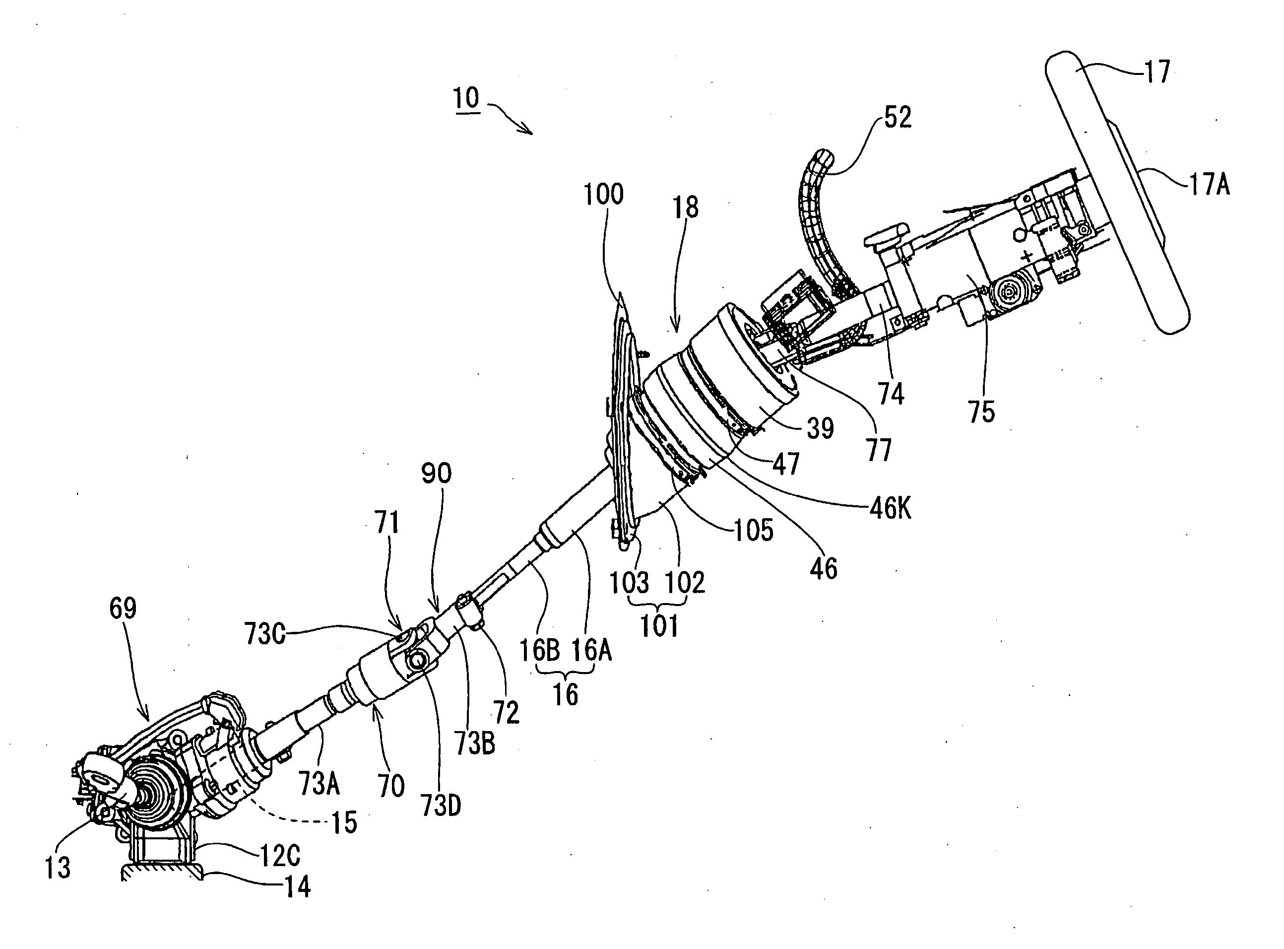
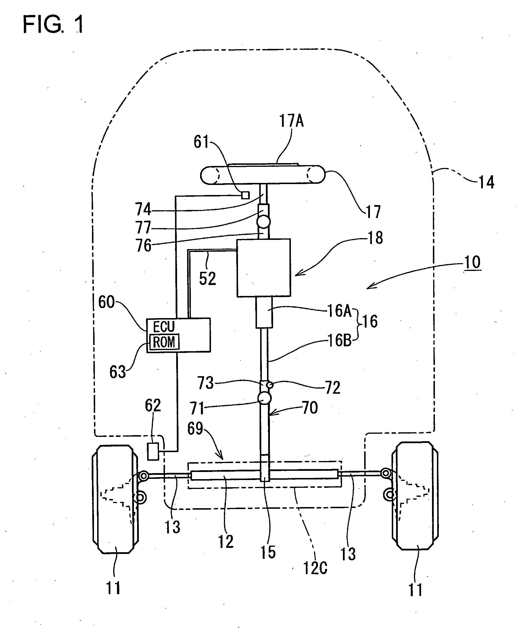
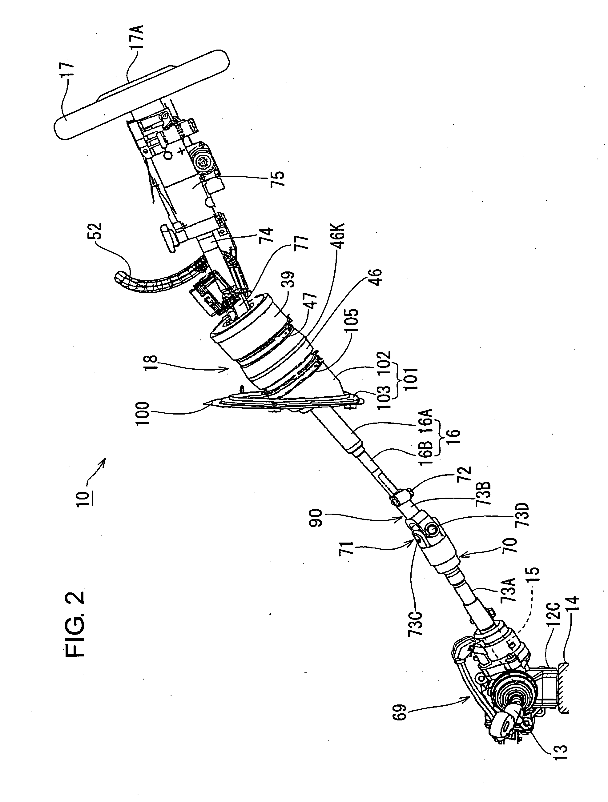
[0008] Accordingly, it is a primary object of the present invention to provide an improved steering device which is capable of firmly securing a case outer component against rotation relative to a vehicle body even in any car model.
[0009] Another object of the present invention is to provide an improved steering device capable of being assembled to a vehicle body without damaging a rubber boot covering an actuator which is provided on an intermediate portion of a steering shaft for altering the transmission ratio in rotation from a steering handle to a steering gear unit.
[0013] With the construction in the second aspect, since the lower end corner portion of the actuator is covered with the cap which is higher in elasticity, the damage of the rubber boot can be avoided even when the lower end corner portion of the actuator is brought into hit on the rubber boot during the assembling work.

Problems solved by technology

Further, the problem attendant on the wire of the V-letter shape in the prior art steering device no longer arises even in the car models wherein the case outer cylindrical component and the dashboard are relatively far from each other.

Method used


Image

  • Steering device
  • Steering device
  • Steering device

Examples


first embodiment

Modifications of First Embodiment

[0077] The present invention is not limited to the foregoing embodiment. For example, the following modifications are encompassed within the technical scope of the present invention, and besides the following modifications, the present invention can be practiced in various forms without departing from the gist thereof. (1) Although in the foregoing first embodiment, the rubber boot 120 is fixed to the dashboard 100 through the boot insertion bracket 101, a flange for example may be provided to overhang from the circumferential surface of the rubber boot 120 and may be fixed to the opening edge portion of the through hole 100A formed on the dashboard 100. (2) Although in the foregoing embodiment, the upper end portion of the rubber boot 120 is fixed with the clamp ring 47 to the case outer cylindrical component 41, adhesive may be used to secure the upper end portion of the rubber boot 120 fitted on the case outer cylindrical component 41. (3) Althoug...

second embodiment

Modifications of Second Embodiment

[0099] The present invention is not limited to the foregoing second embodiment. For example, the following modifications are encompassed within the technical scope of the present invention, and besides the following modifications, the present invention may be practiced in various forms without departing from the gist thereof. (1) Although the cap 80 in the foregoing second embodiment covers not only the lower end corner portion of the actuator 18 but also an area adjacent to the center portion of the lower end surface, the cap in the present invention may be constructed to cover the lower end corner portion only of the actuator 18. (2) Although the cap 80 in the foregoing second embodiment takes a roundish dome shape, it may be a conical shape or a pyramid shape. (3) Although in the foregoing second embodiment, the plural support ribs 85D are formed on the lower end surface of the actuator 18 with intervals therebetween, the entire lower end surface...


PUM


Abstract

In a steering device 10, the upper side portion of a rubber boot 120 is fixedly fitted on a case outer cylindrical component 41 of a cable case 39, and the lower side portion of the rubber boot 120 is fixed to a dashboard 100 of a vehicle body 14 over the entire circumference thereof. Thus, the case outer cylindrical component 41 can be secured against rotation more firmly compared with a prior art steering device wherein such a case outer cylindrical component is fixed at two portions thereon by means of a wire of a V-letter shape. Further, the problem attendant on the wire of the V-letter shape in the prior art steering device no longer arises even in the car models wherein the case outer cylindrical component 41 and the dashboard 100 are relatively far from each other. That is, it can be realized to secure the case outer cylindrical component 41 of the cable case 39 against rotation relative to the vehicle body 14 even in any car model.

Description

[0001] This application claims priority under 35 U.S.C. 119 with respect to Japanese Applications No. 2004-257252 and No. 2004-257849 respectively filed on Sep. 3 and 6, 2004. BACKGROUND OF THE INVENTION [0002] 1. Field of the Invention [0003] The present invention relates to a steering device provided with an actuator at an intermediate portion of a steering shaft extending downward from a steering handle for altering the transmission ratio in rotation between upper and lower portions of the steering shaft in dependence on the traveling state. [0004] 2. Discussion of the Related Art [0005] Generally, on the upper surface of an actuator provided in steering devices of this kind, there is provided a cable case of a double cylinder structure, wherein a case inner component composing an inner member of the cable case is fixed to the actuator, whereas a case outer component composing an outer member of the cable case is fixed to the vehicle body. A spiral cable constructed by winding a ...

Claims


Application Information

Patent Timeline
IPC IPC(8): B62D5/04B60R13/08B62D1/16
CPCB60R13/0256B62D1/166B62D1/16B60R13/0853
Inventor KANAYAMA, YUKIHIKOKATO, KENJIHASEGAWA, ISAOHAYASHI, KENJI
Owner JTEKT CORP
Learn More