
Crawler tractor

a tractor and trailer technology, applied in the field of trailers, can solve the problems of large number of components, difficult assembling operation, and difficult assembly operation, and achieve the effects of simplifying the configuration of the machine body, improving maintainability, and easy assembling into the machine body

Inactive Publication Date: 2006-03-09
YANMAR CO LTD
View PDF7 Cites 13 Cited by
  • Summary
  • Abstract
  • Description
  • Claims
  • Application Information

AI Technical Summary

Benefits of technology

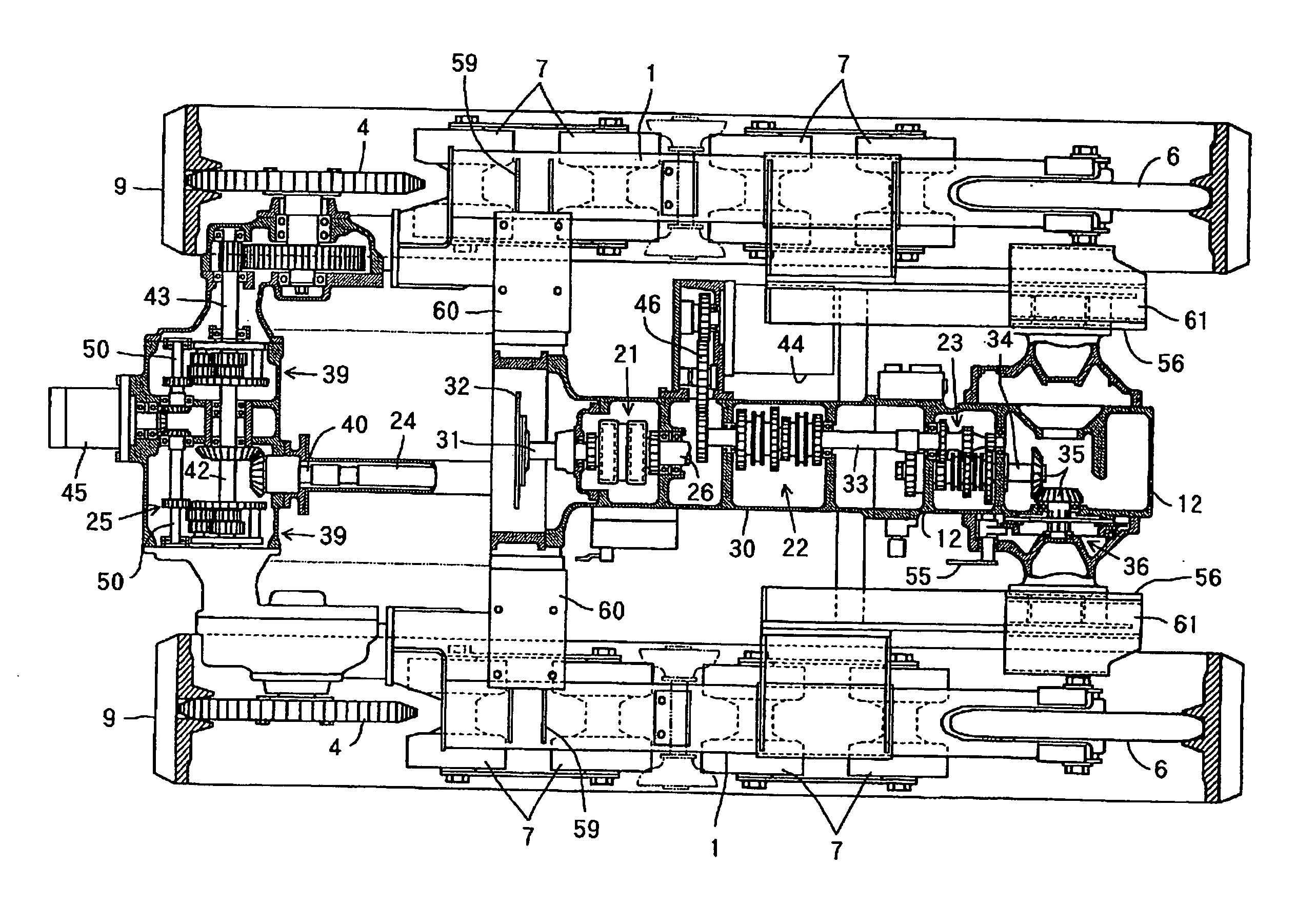
[0003] According to the present invention, a crawler tractor comprises steering mechanisms 44, 45 for staring to rotate a machine body by causing right and left crawler belts 9 to move at differential speed. The steering mechanism 44 is connected to a driving system at a position located behind a reverser mechanism 21 for switching a moving direction of the machine body to forward or rearward. Thereby, even when the moving direction of the machine body is changed from forward to rearward, the steering direction of the steering wheel 18 and the rotating direction of the machine body are kept the same, so that a reversed steering phenomenon is prevented, and an appropriate operation in forward or rearward movement is enabled with a simple structure not requiring an additional mechanism such as a reverse-steering prevention mechanism.
[0004] Further, the crawler tractor comprises travel speed-change mechanisms 22, 23 of gear-switching type for changing travel speed by switching a gear train. An input side of the steering mechanism 44 is connected to a speed-change shaft 33 of the travel speed-change mechanism 22. Thereby, comparing with one in which the speed-change mechanism is directly driven by the engine 10, the steering mechanism 44 can be disposed with fine heat balance without adversely affecting accessories of the engine 10 so as to enable the steering mechanism 44 to be disposed conveniently. Moreover, since the speed change shaft 33 is disposed behind the reverser mechanism 21, a reversed steering wheel can be prevented and a fine rotating operation with the same rotating radius can be obtained irrespective of the speed change operation of a main travel speed-change mechanism.
[0005] Further, the steering mechanism 44 is connected to the steering wheel 18 via a reduction gear 101 and a link mechanism 72 which are mounted in a cantilever manner to a single stay 102 of a steering wheel column 19. Therefore, it is possible to improve the assembling efficiency by mounting the reduction gear 101 and the link mechanism 72 to the single stay 102 in a compact and light-weighted manner, and to miniaturize the steering wheel column 19.

Problems solved by technology

Thereby, a large number of components were required, and the assembling operation was not easy but difficult.

Method used


Image

  • Crawler tractor
  • Crawler tractor
  • Crawler tractor

Examples


Embodiment Construction

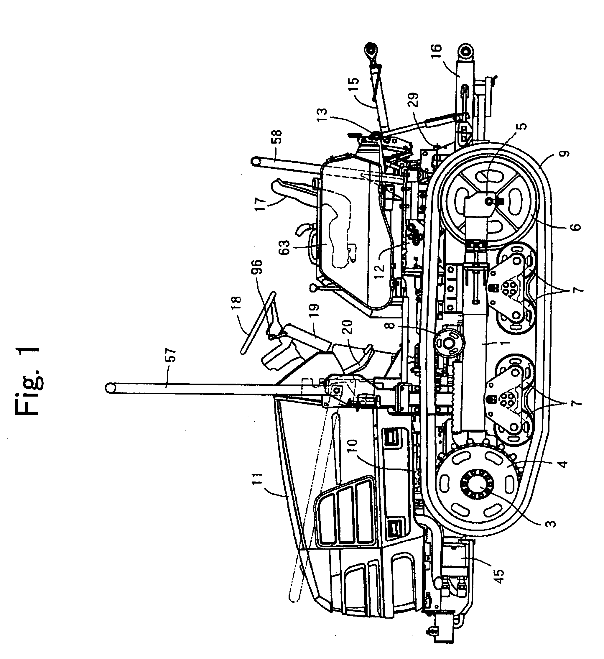
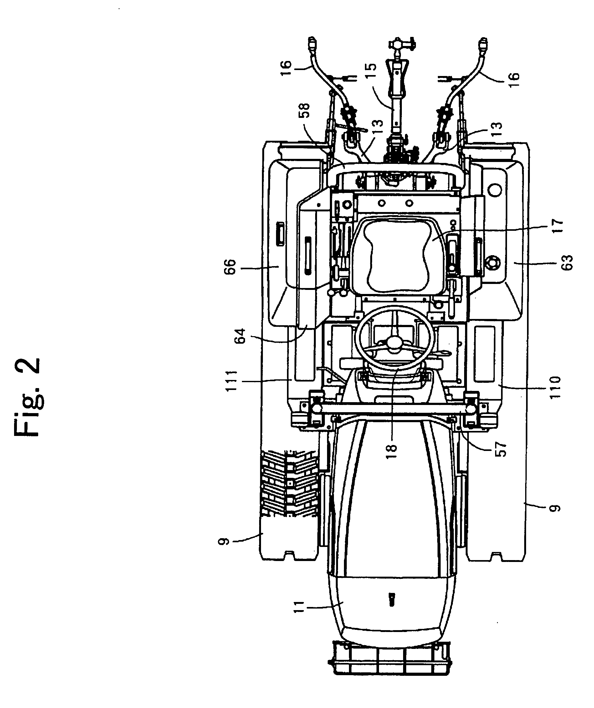
[0073] Hereinafter, an embodiment of the present invention will be described in detail with reference to the drawings. FIG. 1 is a left side view of a crawler tractor, FIG. 2 is a plan view of the same, FIG. 3 is a right side view of the same, FIG. 4 is a front view of the same, FIG. 5 is a rear view of the same, FIG. 6 is a bottom view of the same, and FIG. 7 is a perspective illustration of a vehicle body. In this embodiment, a front transmission case 2 is fixed to the front parts of a pair of right and left square barrel-shaped crawler frames 1, and right and left driving sprockets 4 are pivotally supported on right and left axles 3 of the front transmission case 2. Further, tension rollers 6 are mounted on the rear parts of the crawler frames 1 via tension frames 5, and traveling crawlers 9 are rolled between the driving sprockets 4 and the tension rollers 6 via equalizer rotating wheels 7 and idlers 8, so that a pair of right and left traveling crawler belts 9 are mounted.

[007...


PUM


Abstract

A crawler tractor comprises steering mechanisms (44) (45) for rotating a machine body by causing right and left crawler belts (9) to move differentially. The tractor is characterized in that the steering mechanism (44) is connected to a drive system located behind a reverser mechanism (21) that moves the machine body forward and back. Even when the machine body movement direction is changed from forward to back, the direction of the steering wheel (18) and the direction of the rotation of the machine body are kept the same, so that a reversed steering phenomenon is prevented from occurring, and an appropriate operation in forward or back movement is enabled with a simple structure that does not require an additional mechanism such as a reverse-steering preventions mechanism.

Description

TECHNICAL FIELD [0001] The present invention relates to a crawler tractor having right and left traveling crawlers. BACKGROUND ART [0002] Conventionally, traveling wheels are generally used for the traveling parts of tractors, but in some cases, traveling crawlers are used (for example, JP-A 2001-253362). In the conventional art, in case of that steering mechanisms such as a reduction gear and a conical link mechanism are connected to the steering wheel, the reduction gear mechanism and the conical link mechanism are mounted as separate units to the steering wheel column. Thereby, a large number of components were required, and the assembling operation was not easy but difficult. DISCLOSURE OF THE INVENTION [0003] According to the present invention, a crawler tractor comprises steering mechanisms 44, 45 for staring to rotate a machine body by causing right and left crawler belts 9 to move at differential speed. The steering mechanism 44 is connected to a driving system at a position...

Claims


Application Information

Patent Timeline
IPC IPC(8): B62D11/02B60K15/063B62D11/08B62D11/18B62D33/06B62D49/00B62D49/06B62D55/06
CPCB62D33/0625B62D49/065B62D55/06B62D25/10B60Y2200/25B62D11/183B60K15/063
Inventor AKASHIMA, SUSUMUKOMATSU, MASAKAZU
Owner YANMAR CO LTD
Learn More