Refuse cart lifter with an improved range of rotation

a technology of lifting device and refuse container, which is applied in the direction of packaging, loading/unloading, packaging bottles, etc., can solve the problems of affecting the efficiency of refuse collection, and affecting the safety of rear-loading refuse collection vehicle drivers, so as to improve the operating envelope, improve the efficiency of refuse collection, and save time and energy

Inactive Publication Date: 2006-03-02
BAYNE MACHINE WORKS
View PDF23 Cites 12 Cited by
  • Summary
  • Abstract
  • Description
  • Claims
  • Application Information

AI Technical Summary

Benefits of technology

[0015] The present refuse cart lifter has an improved operating envelope resulting from a wide range of rotation of the lifter faceplate in combination with a unique lifter arm design. This yields a refuse cart lifter that may be capable of being retracted when not in use for increased ground clearance, whil

Problems solved by technology

Refuse containers are often quite heavy, and therefore refuse collection vehicles are generally equipped with refuse container lifting devices to assist the vehicle operator when emptying the refuse containers.
However, a refuse collection vehicle may encounter several different types of refuse containers on a given collection route, and the differences in these refuse containers often require the use of separate lifting devices.
Many prior refuse cart lifters present a wide profile and thus protrude from the refuse collection vehicle so as to interfere with the emptying of commercial dumpsters when they are tipped over the edge of the vehicle hopper.
Protruding cart lifters also created a hazard for the rear-loading refuse collection vehicle driver when backing up, and the side-loading refuse collection driver when navigating narrow roadways, such as alleys.
Another problem in the refuse cart lifter industry is that cart lifters typically hang down from the refuse collection vehicle, and therefore reduce the vehicle's ground clearance, particularly on uneven ground.
Yet another issue involves refuse compaction cycles.
Prior cart lifters continuously dump refuse into the portion of the vehicle hopper closest to the refuse cart lifter because these lifters cannot empty the refuse cart a substantial distance into the hopper when dumping.
A further issue involves maintenance of the lifter.
Elevated hydraulic loads associated with some lifters correspond to increased wear and strain on cart lifter systems.
Also, some lifter motor designs are readily susceptible to damage fr

Method used


Image

  • Refuse cart lifter with an improved range of rotation
  • Refuse cart lifter with an improved range of rotation
  • Refuse cart lifter with an improved range of rotation

Examples


first embodiment

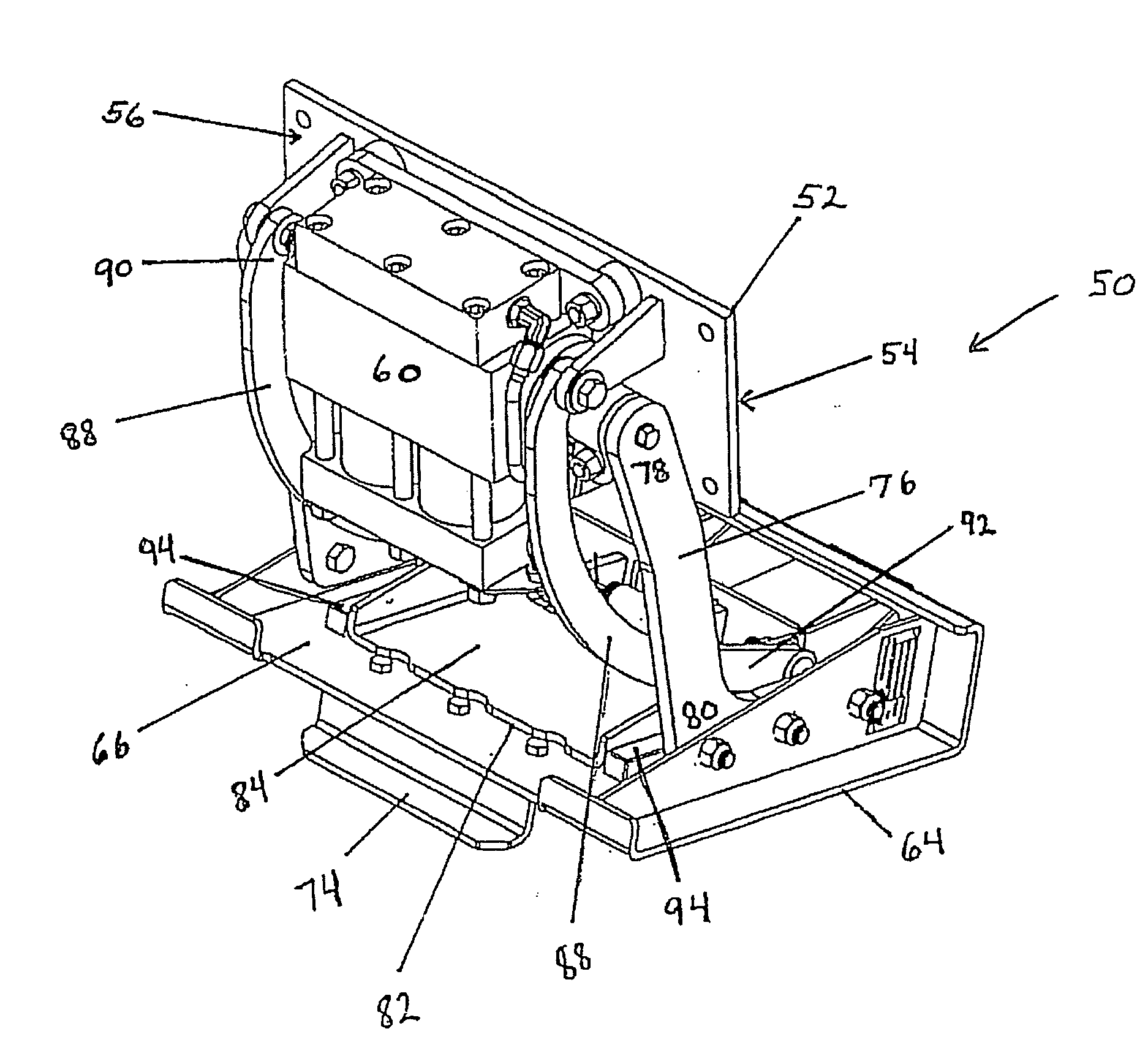
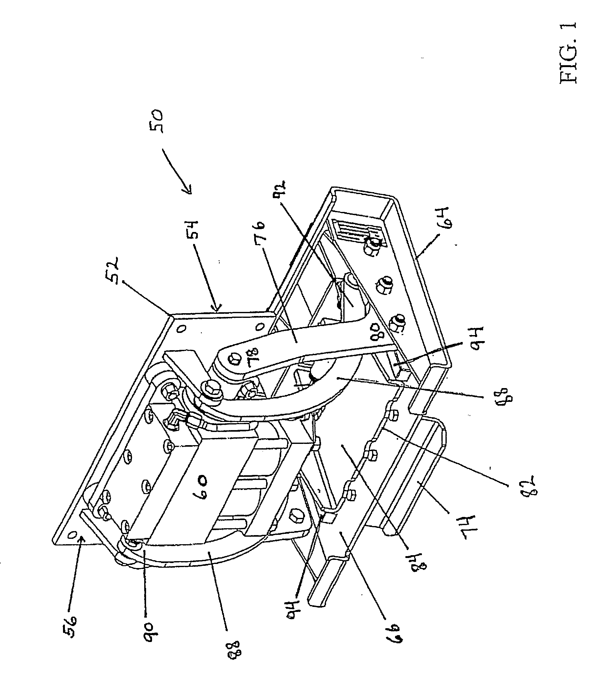
[0058]FIG. 3 depicts the present refuse cart 50 lifter shown in a dumping position, which is the extreme opposite of the retracted position depicted in FIG. 1. In FIG. 3, the motor 60 has further rotated rotatable shaft 62 and attached lifting arms 76 preferably past a vertical position. The resulting angle of the first end 78 of lifting arms 76 away from the back side 54 of the baseplate 52 (see FIG. 4) or towards the hopper if the present refuse cart lifter 50 is mounted on a refuse collection vehicle (see FIG. 17), combined with the design of the lifting arms 76 that directs the second end 80 of lifting arms 76 even further away from the back side 54 of the baseplate 52 serves to swing faceplate 64 to a position above and substantially behind baseplate 52. Lifting arm 76 design directs the second end 80 of lifting arms 76 away from the back side 54 of the baseplate 52 (see FIG. 1) by offsetting the second end 80 of lifting arm 76 from lifting arm 76 using, for example, a curve or...

second embodiment

[0071] the present refuse cart lifter 150 is depicted in FIGS. 18 through 23. FIG. 18 depicts refuse cart lifter 150 positioned in a retracted position. The motor 160 is affixed to the front side 156 of the baseplate 152. The motor depicted is a dual rack, single pinion hydraulic actuator capable of 210 degrees of rotation. The rear side 154 of baseplate 152 can be attached to a refuse collection vehicle or a large refuse collection container. Dual lifting arms 176 are attached to the rotatable shaft 162 (see FIG. 20) of motor 160 at a first end 178 of the lifting arms 176. The second end 180 (see FIG. 23) of lifting arms 176 are attached to faceplate 164.

[0072] As lifter 150 lifting arms 176 are rotated, attached faceplate 164 swings in a corresponding arc as lifter 150 is either extended (see FIGS. 19 and 20) or retracted (see FIG. 18), similar to the operation of the first embodiment relating to refuse cart lifter 50. Unlike the first embodiment of the present lifter 50 that uses...


PUM


Abstract

A lifter is disclosed which allows for an improved operating envelope of the faceplate. The lifter utilizes a motor having 210 degrees of rotation and lifting arms of a unique geometry to rotate a faceplate from a retracted position below and substantially behind the lifter baseplate to a dumping position above and substantially behind a lower hopper edge for the purpose of dumping refuse carts into a refuse collection vehicle. This dumps refuse further into the vehicle hopper, which minimizes the number of packing cycles required on a collection route. A faceplate is attached to the motor using two lifting arms. The faceplate has a fixed upper hook and may be configured with a sliding, retractable lower hooking mechanism or a spring loaded, cam actuated rotating hook mechanism. The faceplate may include multiple sets of attachment points for attaching the lifting arms to facilitate the mounting of the lifter on a refuse collection vehicle over a range of heights without necessitating replacement of the lifting arms.

Description

RELATED APPLICATIONS [0001] This application is a continuation-in-part of U.S. patent application Ser. No. 10 / 803,281, entitled “Refuse Cart Lifter With An Improved Range Of Rotation” (Attorney Docket 14893US02), filed Mar. 18, 2004, which makes reference to, claims priority to, and claims the benefit of U.S. Provisional Patent Application Ser. No. 60 / 455,546, entitled “Refuse Collection Cart Lifter With An Improved Range Of Rotation” (Attorney Docket 14893US01), filed Mar. 18, 2003, the complete subject matter of which is hereby incorporated herein by reference in its entirety.FEDERALLY SPONSORED RESEARCH OR DEVELOPMENT [0002] [Not Applicable][MICROFICHE / COPYRIGHT REFERENCE][0003] [Not Applicable]BACKGROUND OF THE INVENTION [0004] The present invention relates to refuse container lifting devices, and in particular to refuse cart lifting devices. Refuse containers are often quite heavy, and therefore refuse collection vehicles are generally equipped with refuse container lifting dev...

Claims


Application Information

Patent Timeline
IPC IPC(8): B65F3/02B65F3/04
CPCB65F2003/0246B65F3/046
Inventor BAYNE, BILLY K.BIGGERSTAFF, JIMMY M.
Owner BAYNE MACHINE WORKS
Why Eureka
Try Eureka