
High-directivity spurline directional coupler

a directional coupler and high-directivity technology, applied in the field of couplings, can solve the problems of deteriorating isolation and departing, and achieve the effect of improving the directivity of the coupler

Inactive Publication Date: 2006-03-02
INTEGRATED SYST SOLUTION +1
View PDF3 Cites 9 Cited by
  • Summary
  • Abstract
  • Description
  • Claims
  • Application Information

AI Technical Summary

Benefits of technology

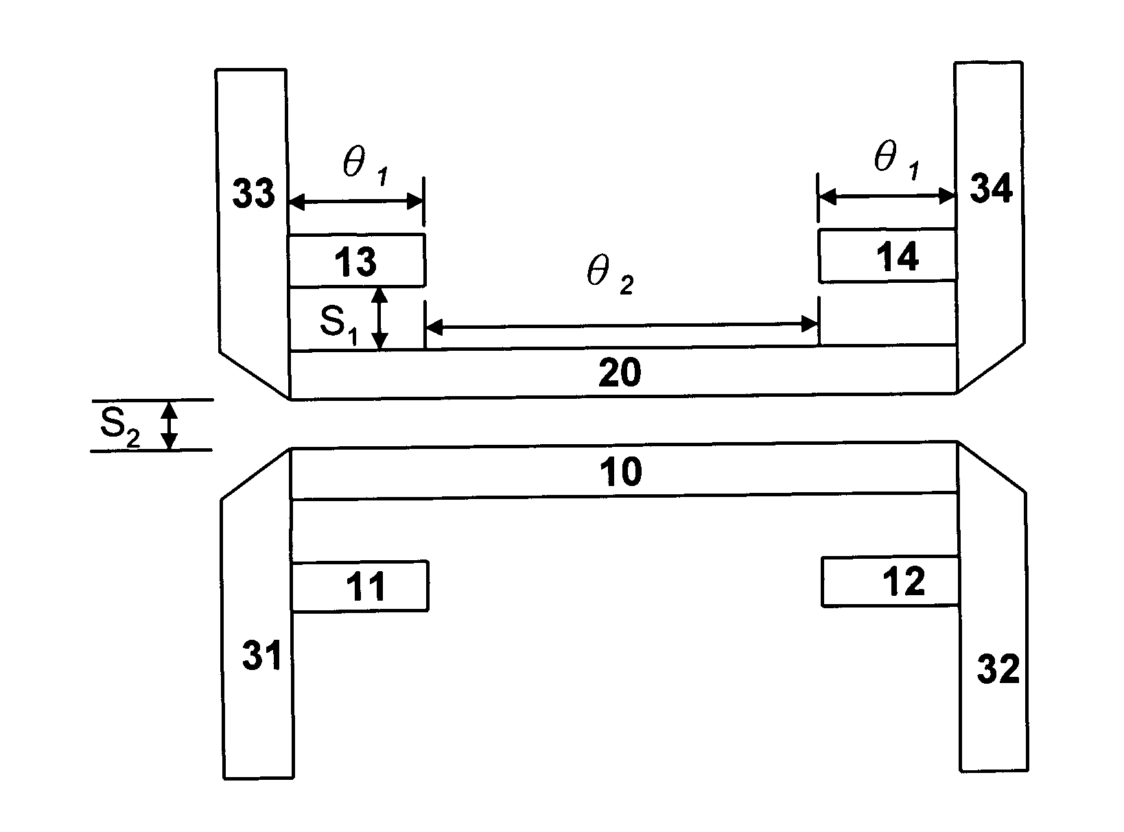
[0006] In view of the problems set forth above, the primary object of the invention is to provide a spurline directional coupler that adds respectively a spur-like sub-coupler on two ends of the primary coupler in a symmetrical or asymmetrical manner. By controlling the length and the spacing of the sub-coupler, an isolation zero can be generated in the desired frequency band, thereby improving the directivity of the coupler.
[0008] The isolation of the typical parallel coupler deteriorates as frequency increases. The coupler of the invention can generate an isolation zero in the desired frequency to improve the directivity due to the capacitive effects of sub-coupling sections.

Problems solved by technology

Another problem is that the isolation is deteriorated as frequency increases.
These techniques have drawbacks of either departing away from the planar structure due to the addition of lump elements, or requiring special fabrication procedures for another dielectric overlay or wiggling the conductor edges.

Method used


Image

  • High-directivity spurline directional coupler
  • High-directivity spurline directional coupler
  • High-directivity spurline directional coupler

Examples


Embodiment Construction

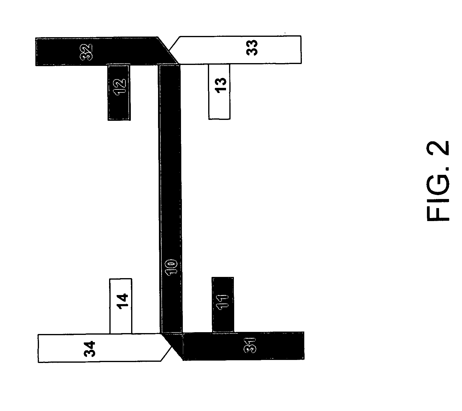
[0022] The spurline directional coupler according to the invention aims to generate high directivity. Referring to FIG. 1, it includes a primary coupling section and a sub-coupling section. The primary coupling section includes a first coupling section 10 and a second coupling section 20. The sub-coupling section includes a first sub-coupling section 11, a second sub-coupling section 12, a third sub-coupling section 13, and a fourth sub-coupling section 14.

[0023] The first coupling section 10 has one end connected to a first signal transmission section 31 and another end connected to a second signal transmission section 32. The second coupling section 20 has one end connected to a third signal transmission section 33 and another end connected to a fourth signal transmission section 34. The second coupling section 20 is substantially in parallel with the first coupling section 10. They are not in contact with each other to form a parallel coupling.

[0024] The first sub-coupling sect...


PUM


Abstract

A spurline directional coupler includes a first coupling section and a second coupling section that are in parallel with each other for coupling, and a first sub-coupling section and a second sub-coupling section coupled with the first coupling section, and a third sub-coupling section and a fourth sub-coupling section coupled with the second coupling section. The parallel coupling relationship between the coupling section and the sub-coupling sections generates a capacitive effect thereby may improve isolation and directivity of the spurline directional coupler.

Description

FIELD OF THE INVENTION [0001] The present invention relates to a coupler and particularly to a spurline directional coupler that uses transmission lines to generate a capacitive compensation effect to improve the directivity of the coupler. BACKGROUND OF THE INVENTION [0002] A directional coupler is a widely-used element in microwave circuits such as a phase shifter, balanced amplifier, balanced mixer, power divider, modulator, power detector and the like. Particularly in microwave integrated circuits (MIC), microstrip parallel-coupled lines are commonly used to implement the directional coupler. They are required to have up-to −3 dB coupling amount and more than 40-dB isolation, that is, they must have high directivity. [0003] Because of manufacturing constraints in minimum line spacing, the coupling amount of a single microstrip parallel coupler provided in the prior art is about −10 dB. To increase the coupling amount, a multi-section, multi-figure or multi-layer structure has to...

Claims


Application Information

Patent Timeline
Patent Type & Authority Applications(United States)
IPC IPC(8): H01P5/18
CPCH01P5/187H01P5/185
Inventor CHANG, SHENG-FUHCHEN, JIA-LIANGWU, CHUAN-TINGTSAI, JUO-RUITSAI, ZONG-HSIANCHEN, HUNG-CHENGTANG, SHU-FENCHEN, ALBERT
Owner INTEGRATED SYST SOLUTION
Learn More