
Active photosensitive structure with buried depletion layer

Active Publication Date: 2006-03-02
MICRON TECH INC
View PDF11 Cites 51 Cited by
  • Summary
  • Abstract
  • Description
  • Claims
  • Application Information

AI Technical Summary

Benefits of technology

[0013] In accordance with one aspect of the invention, the pixel cell can perform a charge accumulation mode simultaneously with performing a readout of the pixel, allowing for automatic light control operations.

Problems solved by technology

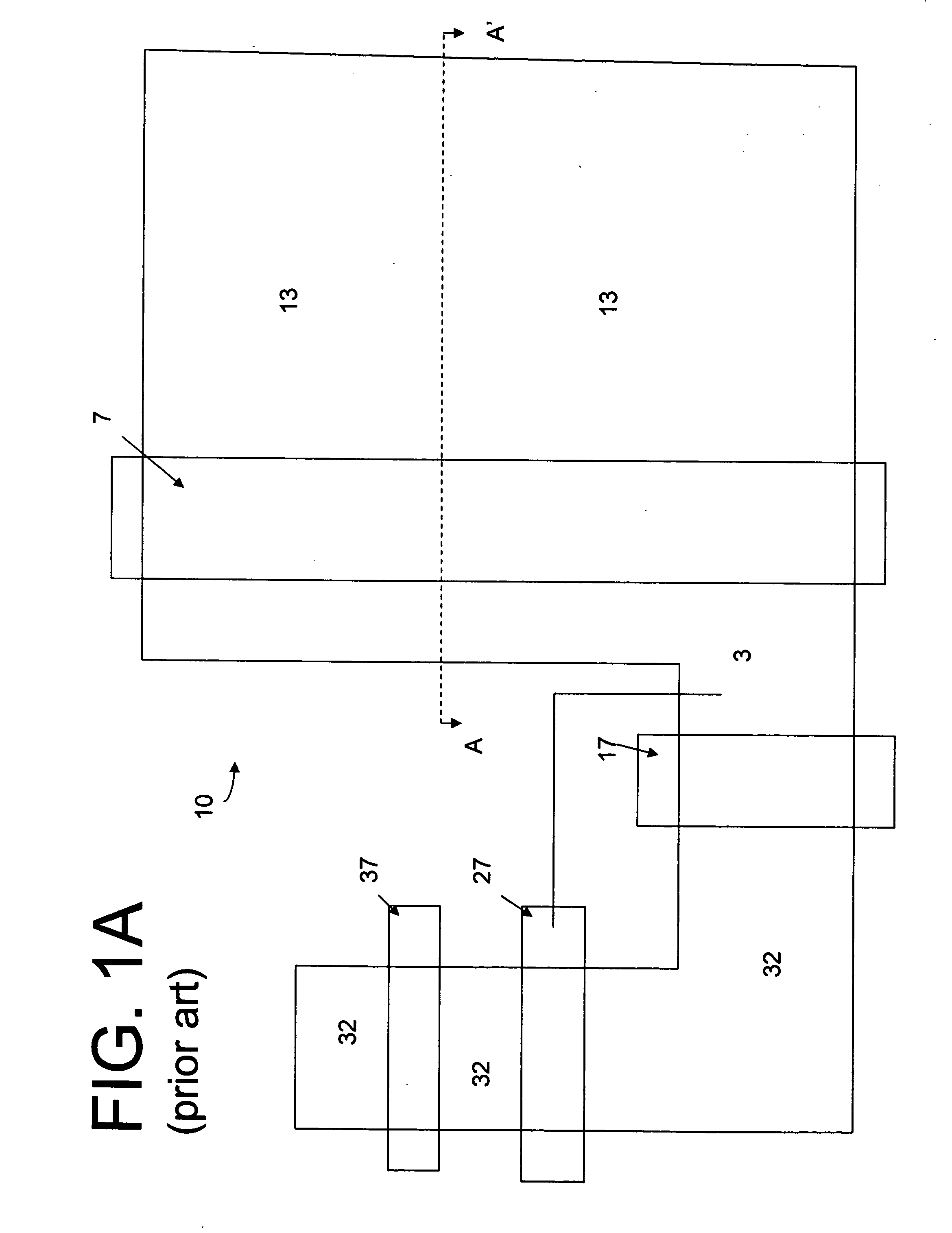
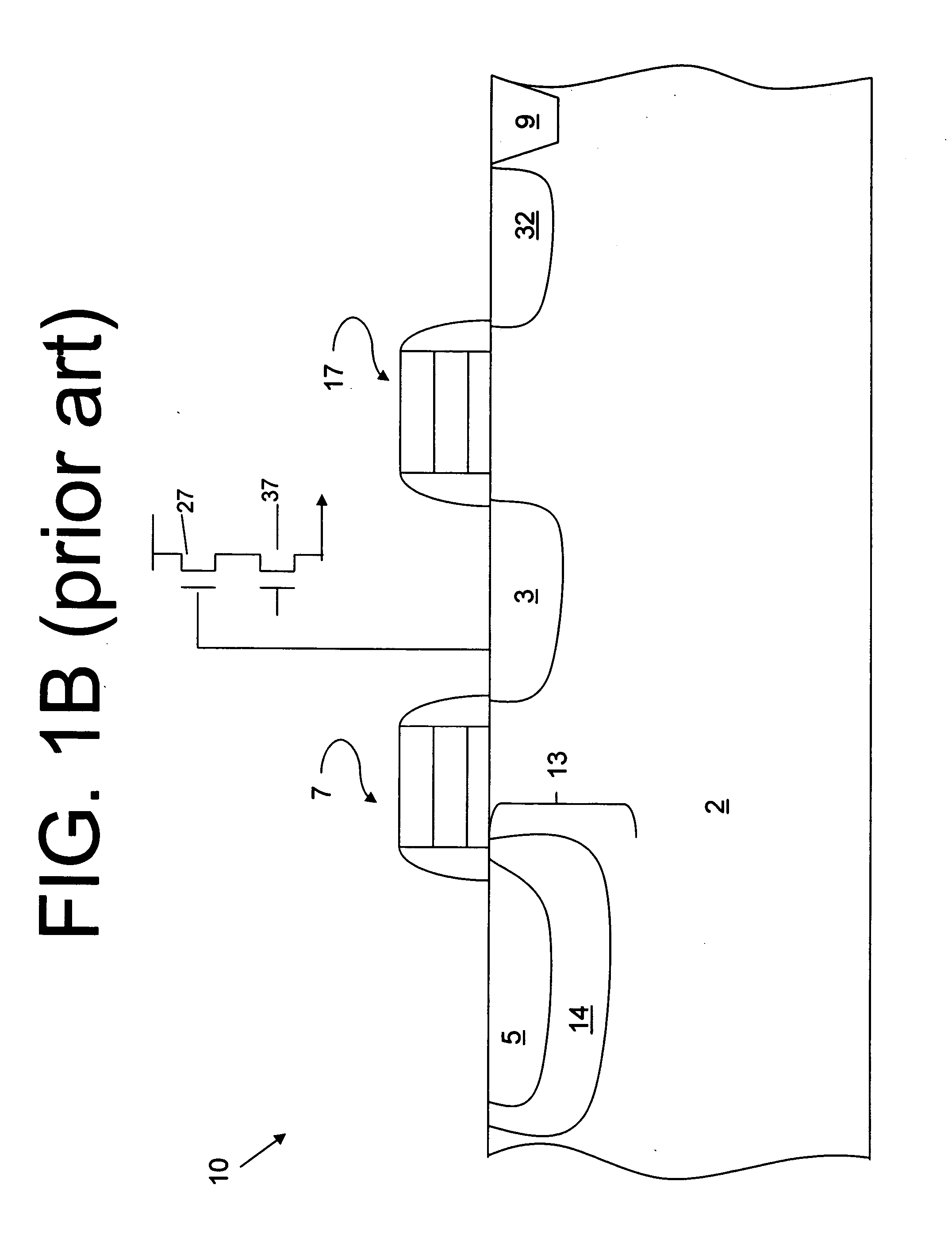
This incomplete transfer creates lag, and can also lead to saturation of the photodiode 13 due to the presence of excess charge.

Method used


Image

  • Active photosensitive structure with buried depletion layer
  • Active photosensitive structure with buried depletion layer
  • Active photosensitive structure with buried depletion layer

Examples


Embodiment Construction

[0022] In the following detailed description, reference is made to the accompanying drawings, which form a part hereof, and in which is shown by way of illustration specific embodiments in which the invention may be practiced. These embodiments are described in sufficient detail to enable those skilled in the art to practice the invention, and it is to be understood that other embodiments may be utilized, and that structural, logical and electrical changes may be made without departing from the spirit and scope of the present invention.

[0023] The term “substrate” is to be understood as a semiconductor-based material including silicon, silicon-on-insulator (SOI) or silicon-on-sapphire (SOS) technology, doped and undoped semiconductors, epitaxial layers of silicon supported by a base semiconductor foundation, and other semiconductor structures. Furthermore, when reference is made to a “substrate” in the following description, previous process steps may have been utilized to form regi...


PUM


Abstract

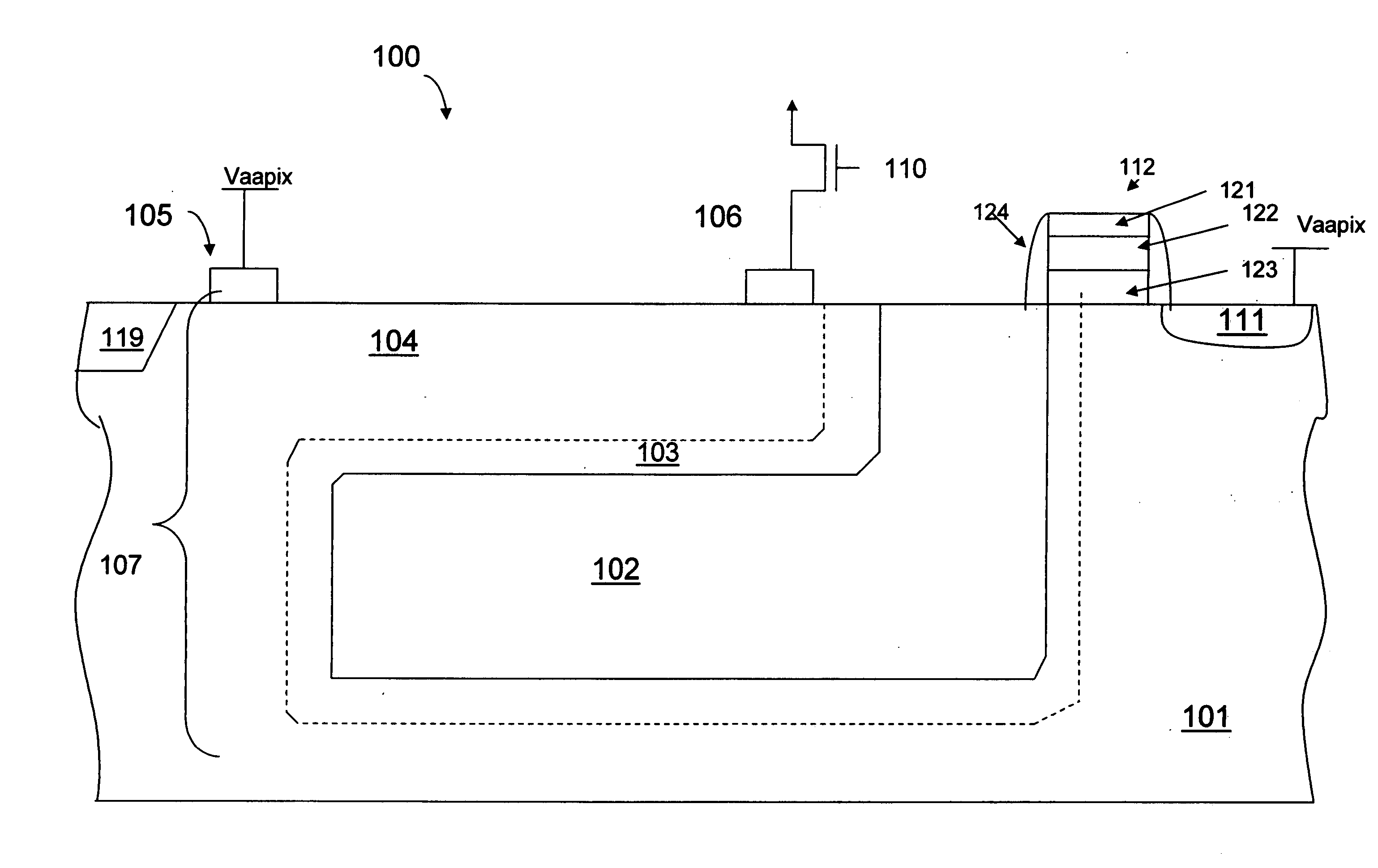
An imager pixel has a photosensitive JFET structure having a channel region located above a buried charge accumulation region. The channel region has a resistance characteristic that changes depending on the level of accumulated charge in the accumulation region. During an integration period, incident light causes electrons to be accumulated inside the buried accumulation region. The resistance characteristic of the channel region changes in response to a field created by the charges accumulated in the accumulation region. Thus, when a voltage is applied to one side of the channel, the current read out from the other side is characteristic of the amount of stored charges.

Description

FIELD OF THE INVENTION [0001] The present invention relates to the field of semiconductor devices and, in particular, to an active pixel photosensitive structure. BACKGROUND OF THE INVENTION [0002] A CMOS imager includes a focal plane array of pixel cells, each cell includes a photosensor, for example, a photogate, photoconductor or a photodiode overlying a substrate for producing a photo-generated charge in a doped region of the substrate. Typical CMOS imager pixel cells have either a three transistor (3T) or four transistor (4T) design. The 4T design is preferred over the 3T because it reduces the number of “hot” pixels in an array (those that experience increased dark current), and it diminishes the kTC noise that 3T designs may experience with the readout signals. [0003] In a CMOS imager, the active elements of a pixel cell, for example a four transistor pixel, perform the necessary functions of (1) photon to charge conversion; (2) transfer of charge to a floating diffusion regi...

Claims


Application Information

Patent Timeline
IPC IPC(8): H01L21/00H01L31/062
CPCH01L31/1126H01L27/14679H01L31/10
Inventor JERDEV, DMITRIKHALIULLIN, NAIL
Owner MICRON TECH INC
Learn More