
Cable television reverse amplifier

Active Publication Date: 2006-02-23
TIMES FIBER COMM
View PDF11 Cites 10 Cited by
  • Summary
  • Abstract
  • Description
  • Claims
  • Application Information

AI Technical Summary

Problems solved by technology

A problem exists with these prior art amplifiers, in applications where one desires to connect a reverse amplifier to the output of a forward amplifier for providing for amplification of the lower band signals along with passing the amplified higher band signals from the forward amplifier.

Method used


Image

  • Cable television reverse amplifier
  • Cable television reverse amplifier
  • Cable television reverse amplifier

Examples


Embodiment Construction

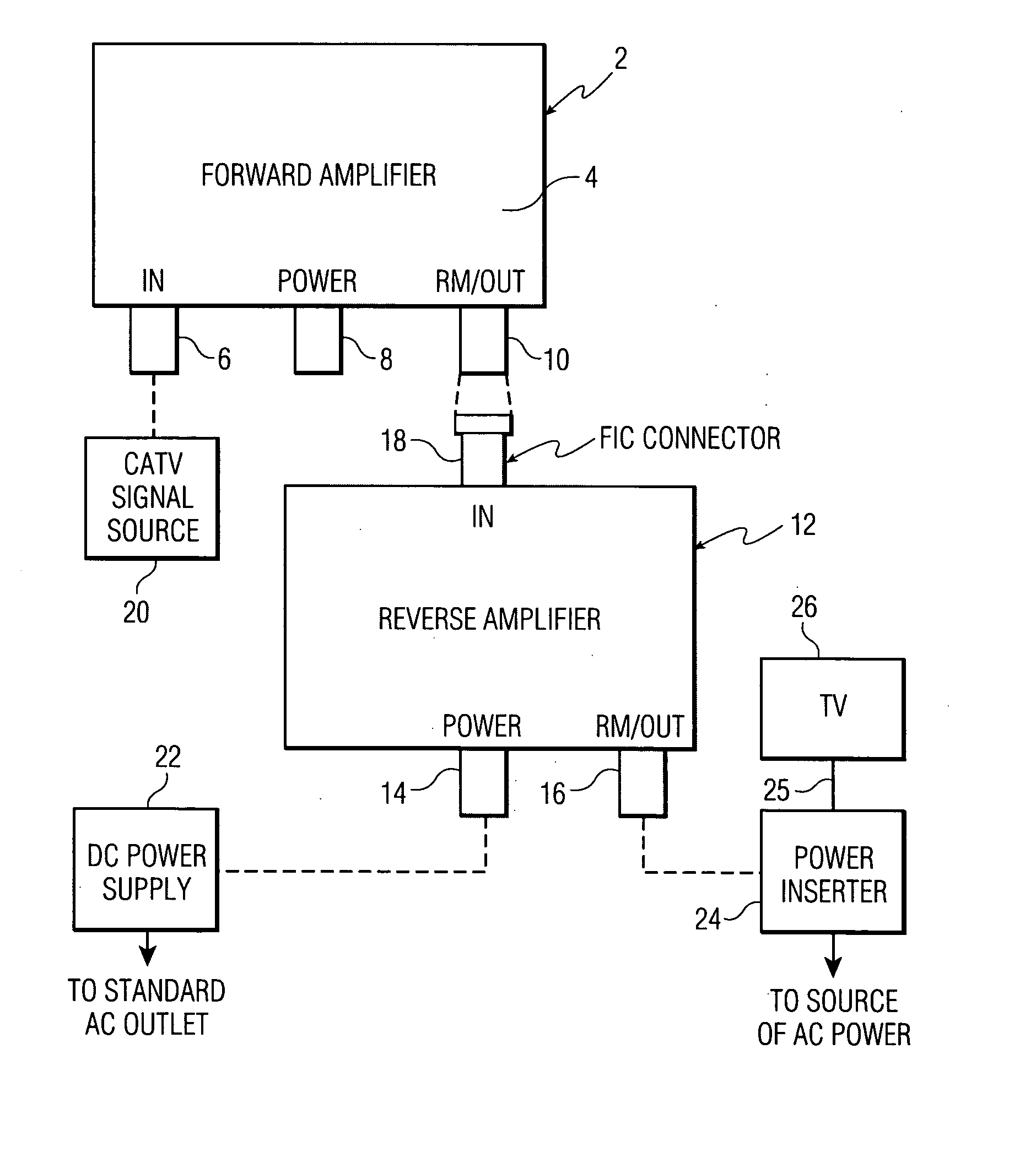
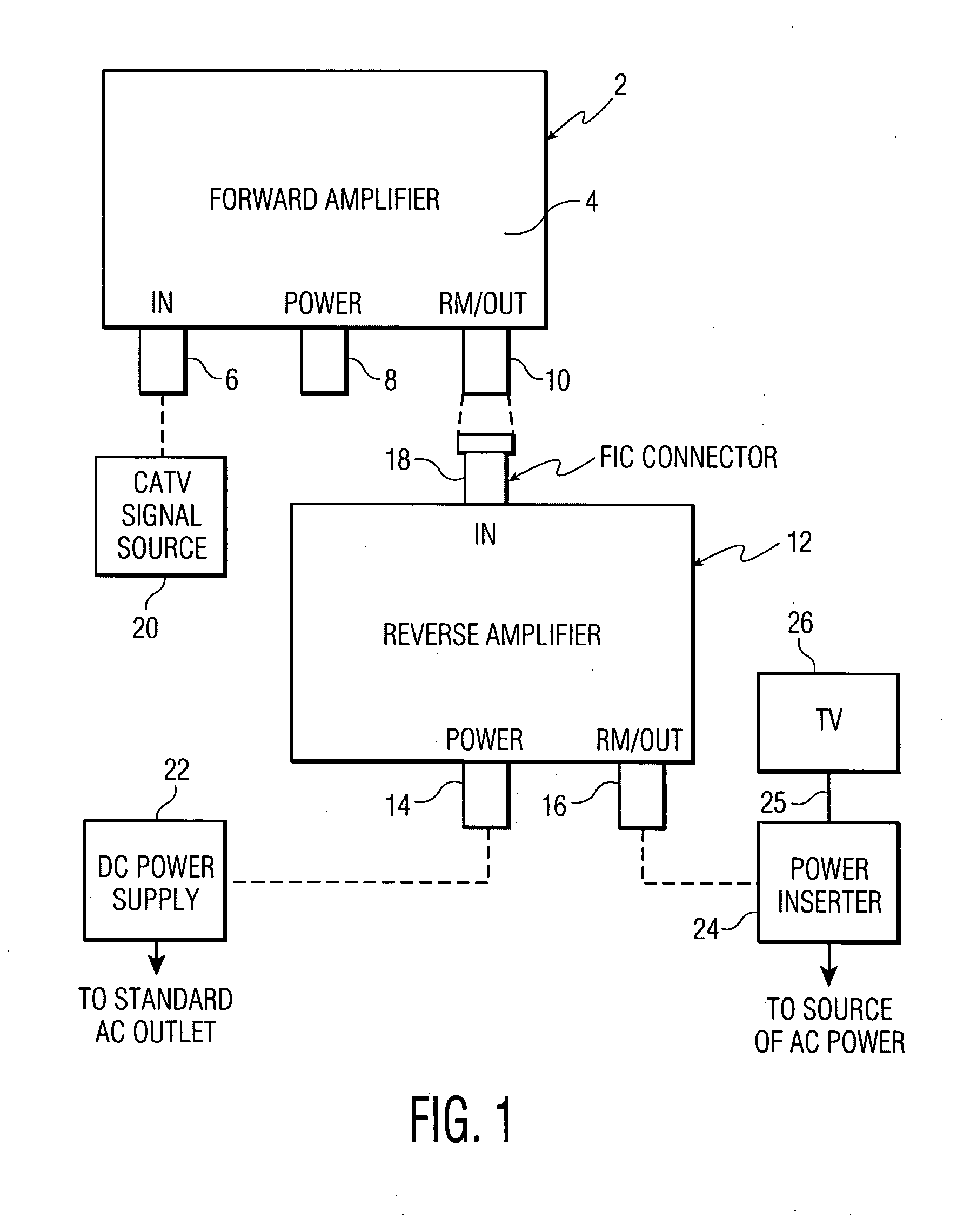
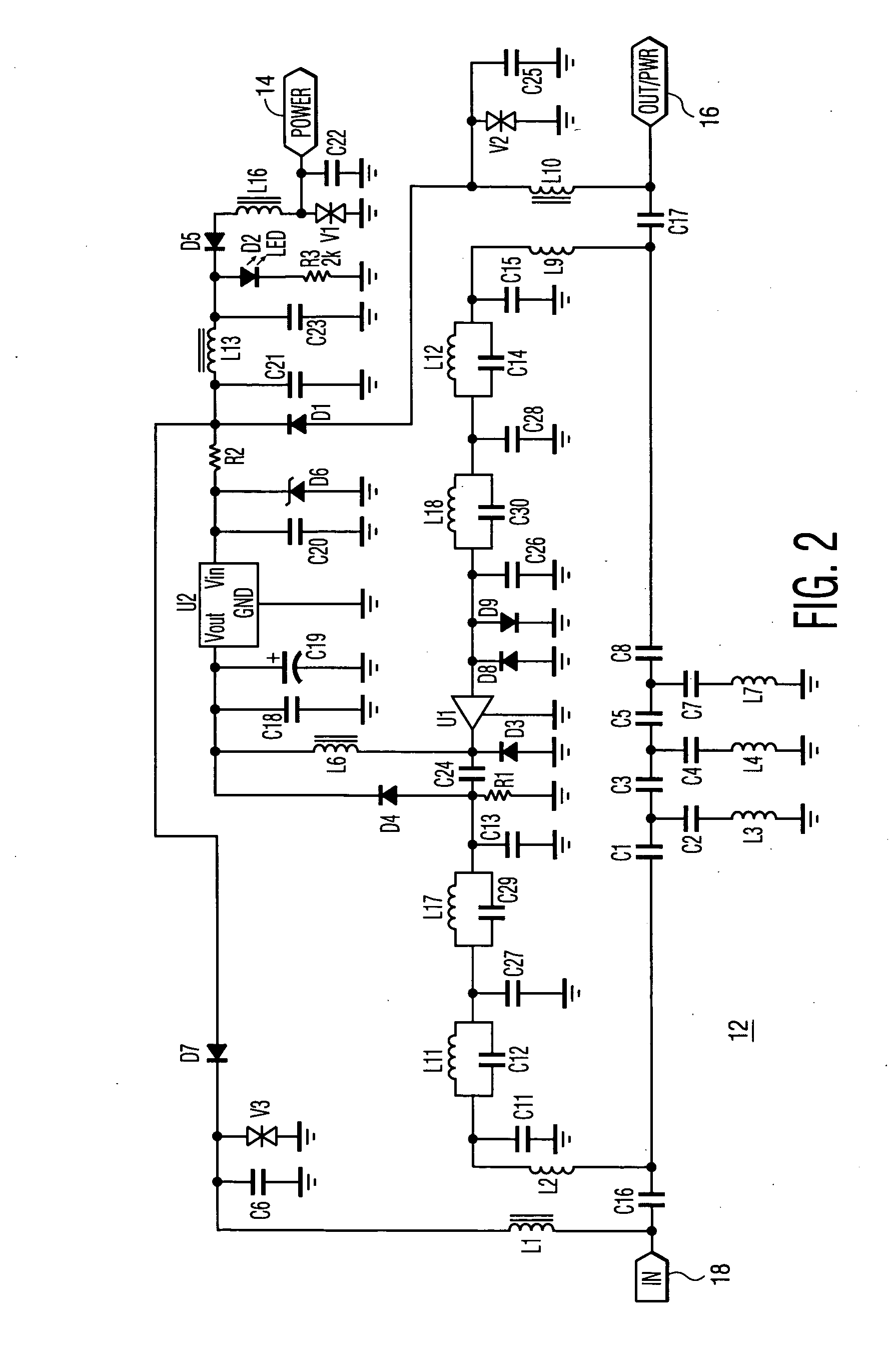
[0008] With reference to FIG. 1, a forward amplifier 2 includes protruding from a housing 4, a 75 ohm female signal input connector 6, a 75 ohm female power input connector 8, and a 75 ohm signal output connector 10, in this example. Typically connectors 6, 8, and 10 are provided by 75 ohm female F-port connectors, in this example. In one embodiment of the invention, a reverse amplifier 12 includes 75 ohm female power and signal output F-port connectors 14, 16, respectively, in this example, and an FIC port connector 18 at a signal input. The FIC port connector 18 of the reverse amplifier 12 can be directly connected to the female F-port output connector 10 of forward amplifier 2, thereby eliminating the need for using a jumper cable having an F-type male connector at each end for electrically connecting the aforesaid ports together. For purposes of this invention, an FIC-port connector is defined as a connector configured for direct mounting upon a housing of an electrical or elect...


PUM


Abstract

A signal input port of a reverse amplifier is provided by an FIC connector, for direct connection to an F-port output of a forward amplifier, thereby eliminating the need for jumper cables. Also, via this connection, the reverse amplifier remotely provides power to the forward amplifier.

Description

RELATED APPLICATION [0001] The present invention is related to and takes priority from U.S. Utility Patent Application Ser. No. 60 / 603,145, filed on Aug. 20, 2004, for “CABLE TELEVISION REVERSE AMPLIFIER.”FIELD OF THE INVENTION [0002] The present invention relates generally to amplifiers, and more specifically to cable television reverse amplifiers. BACKGROUND OF THE INVENTION [0003] It is known in the cable television art to provide a forward amplifier for typically amplifying signals from 52 MHz to 1.0 GHz and passing lower frequency signals without amplification. Forward amplifiers are used to overcome splitter loss, for example, typically in a user's home, in order to amplify the television signals supplied to the user's television set. A cable television reverse amplifier is typically used to amplify signals between 5 MHz to 42 MHz, which represent lower band frequency signals mainly for the transmission of data. A problem exists with these prior art amplifiers, in applications...

Claims


Application Information

Patent Timeline
Patent Type & Authority Applications(United States)
IPC IPC(8): H04N7/173
CPCH03F3/189H04N7/17309H04N7/102H03F3/62
Inventor SHAPSON, JAY F.
Owner TIMES FIBER COMM
Learn More