
Method and terminal for detecting fake and/or modified smart card

a smart card and terminal technology, applied in the field of methods and terminals for detecting fake and/or modified smart cards, can solve the problems of terminal according, inability to detect a smart card emulating another smart card, and high cost of temper resistance and other counter measures normally adopted for dedicated terminals (i.e. atms)

Active Publication Date: 2006-02-23
NXP BV
View PDF6 Cites 157 Cited by
  • Summary
  • Abstract
  • Description
  • Claims
  • Application Information

AI Technical Summary

Benefits of technology

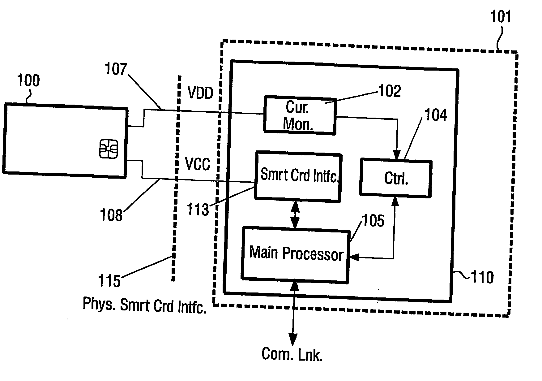
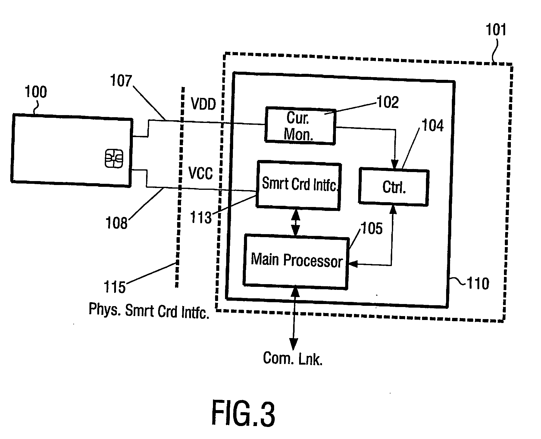
The invention provides a method and terminal for detecting fake and modified smart cards in a physical interface of a terminal. The method involves measuring the current signature of a smart card and comparing it with a unique current signature of a smart card. This allows for the detection of unauthorized applications on a smart card. The method is simple and reliable, and can be used to protect against false cards and rogue applications. The terminal comprises a controller and current monitor for performing the current measurements and determining the difference between the current signatures. The invention also includes a computer-readable medium with instructions for executing the method.

Problems solved by technology

The cost of temper resistant and other counter measures normally adopted for dedicated terminals (i.e. ATMs) are considered to complex and / or expensive for the low cost home terminals.
However, a typical security attack on genuine terminals / sub-terminals is to use a smart card emulating the function of a valid card and / or use a modified smart card, e.g. modified in order to gain access to otherwise restricted services, functions, etc in a terminal.
The terminal according to the above-mentioned patent specification is not able to detect a smart card emulating another smart card, i.e. when no external circuit is attached thereto with wires.

Method used


Image

  • Method and terminal for detecting fake and/or modified smart card
  • Method and terminal for detecting fake and/or modified smart card
  • Method and terminal for detecting fake and/or modified smart card

Examples


Embodiment Construction

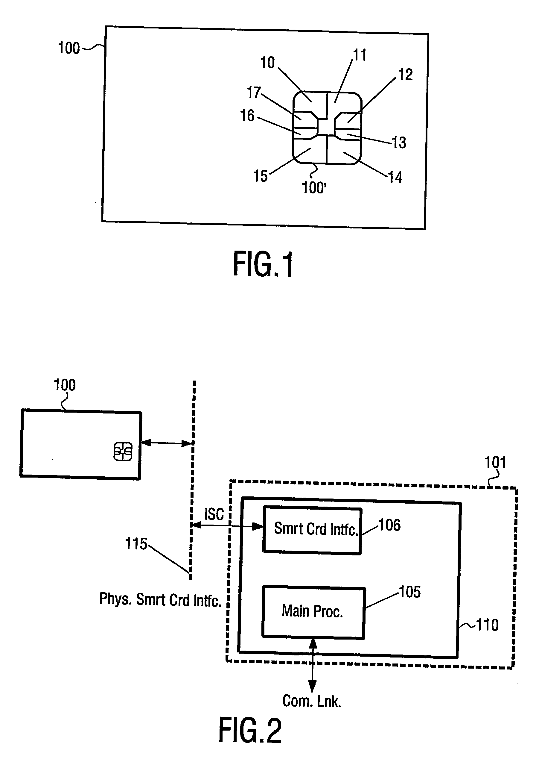
[0050]FIG. 1 schematically illustrates a typical smart card. Shown is a security card / a smart card (100) that is well known in the prior art. Typically the card (100) has the form of standard size credit card, although the form, layout, size, etc. may vary. The card (100) typically comprises embedded memory, a processor / controller and input / output (I / O) used for communication with an appropriate card reader / (sub-)terminal (not shown) via a number of contacts (100′). The shown contacts (100′) (the size of which is exaggerated / enlarged for illustrative purposes) complies with the standard of ISO 7816 part 2 and comprises power supply (10), ground (11), three optional contacts / pins (12, 14, 15) that may be used for different functionality dependent on the specific card, a bi-directional input / output pin (13), check (16) and reset (17). All of these signals are provided by a terminal, receiving the card, to the smart card (100), and the terminal is expected to monitor the bi-directional...


PUM


Abstract

This invention relates to a method and a terminal for detecting a fake and / or modified smart card inserted into a physical interface of a terminal, the method comprising the steps of performing a sequence of current measurements by a current monitor in order to obtain a first current signature, comparing the obtained first current signature with a second current signature, representing a unique current signature of a smart card, and determining whether a difference exists within a predetermined range between the first current signature and the second current signature.This allows for simple detection of fake and / or modified smart cards. Further, it is possible to detect (and thereby protect against) false cards and / or ‘rouge’ application residing on a smart card.

Description

FIELD OF THE INVENTION [0001] The invention relates to a method, and a corresponding terminal, of detecting a fake and / or modified smart card inserted into a physical interface of a terminal. BACKGROUND OF THE INVENTION [0002] Smart cards are commonly used in a wide range of applications for the purpose of authority check, payment, satellite TV, data storage, etc. As an example the health insurance and banking industries use smart cards extensively. A smart card usually resembles a credit card in size and shape, but typically contains an embedded microprocessor inside. A terminal with a card reader communicates with the microprocessor which controls access to the data on the card. Smart cards may e.g. be used with a smart card reader attached to or located in a personal computer to authenticate a user, etc. Smart card readers can also be found in mobile phones for SIM reading and vending machines. [0003] For a private and / or in-home terminal with a smart card reading capability, suc...

Claims


Application Information

Patent Timeline
Patent Type & Authority Applications(United States)
IPC IPC(8): G06F15/00G06K5/00G06K19/073
CPCG06K5/00G06K19/07372G06K19/073G06K17/00
Inventor BAKER, KEITH
Owner NXP BV
Learn More