
Variable inner volume ratio-type inverter screw compressor

Inactive Publication Date: 2006-02-23
DAIKIN IND LTD
View PDF4 Cites 21 Cited by
  • Summary
  • Abstract
  • Description
  • Claims
  • Application Information

AI Technical Summary

Benefits of technology

[0017] According to the above structure, when the inner volume ratio is variable, the opening degree of the variable inner volume ratio valve is controlled by the control section based on the suction side pressure and the discharge side pressure in the screw compression section and the rotational frequency of the electric motor. Therefore, the inner volume ratio is accurately and easily controlled so that the inner volume ratio achieves the highest compressor efficiency corresponding to the rotational frequency of the electric motor adjusted by the inverter by using a prescribed relation of a compression ratio, the rotational frequency of the electric motor and optimum inner volume ratio.

Problems solved by technology

However, the conventional variable inner volume ratio-mode inverter screw compressor disclosed in JP 3159762 B2 has the following problems.
It is disadvantageous in that the conventional variable inner volume ratio-mode inverter screw compressor is inefficient since capability regulation (unload control) is performed under a partial load capability condition (part-load) by bypassing the fluid on the way of its compression to the suction side through the gap between the variable VI valve 3 and the capacity control valve 4.
It is also disadvantageous in that the valve control mechanism of the conventional variable inner volume ratio-mode inverter screw compressor is complex since the variable VI valve 3 for changing inner volume ratio and the capacity control valve 4 for controlling capacity are provided so that the controlling mechanism of the variable VI valve 3 for the time when inner volume ratio is changed and the controlling mechanism of the capacity control valve 4 for the time when capacity is controlled are required to be provided separately.

Method used


Image

  • Variable inner volume ratio-type inverter screw compressor
  • Variable inner volume ratio-type inverter screw compressor
  • Variable inner volume ratio-type inverter screw compressor

Examples


Embodiment Construction

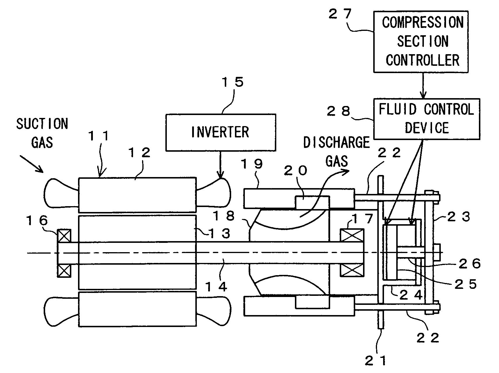
[0025] Hereinafter, this invention will be described in detail by way of preferred embodiments shown in the accompanying drawings. FIG. 1 is a schematic structural diagram showing a variable inner volume ratio-mode inverter screw compressor of this embodiment. It is to be noted that FIG. 1A shows the case when inner volume ratio is low and FIG. 1B shows the case when inner volume ratio is high.

[0026] In FIGS. 1A and 1B, reference numeral 11 denotes an electric motor, which has a stator 12 fixed on a casing (not shown) and a rotor 13 rotating and fixed on one edge side of a main shaft 14. The electric motor 11 is driven by an inverter 15. Both ends of the main shaft 14 are supported by bearings 16 and 17, and a screw rotor 18 is fixed on the other edge side of the main shaft 14. When the main shaft 14 is rotated by the electric motor 11, the screw rotor 18 rotates and suction gas is compressed by the screw groove (not shown) on the outer circumferential surface of the screw rotor. T...


PUM


Abstract

Regulating compression capability to a load is performed by an inverter (15) that regulates revolution number of an electric motor (11). This makes unload control in capability regulation unnecessary, preventing operational efficiency from lowering. Further, a capacity control valve for capacity control is eliminated for a simplified valve control mechanism. Regulating a variable inner volume ratio achieves the highest compressor efficiency corresponding to operating condition (capability). When a low inner volume ratio command is issued, a slide valve (19) is moved by a compression section controller (27) in an axial direction toward the electric motor (11). This advances completion time of a compression step to advance discharge of a compressed gas. When a high inner volume ratio command is issued, the slide valve (19) is moved in an axial direction toward a piston (25), which delays time of completion of compression step to delay discharge of a compressed gas.

Description

TECHNICAL FIELD [0001] The present invention relates to a variable inner volume ratio-mode inverter screw compressor in which an inner volume ratio, the ratio between suction capacity and discharge capacity of a screw compressor, is made variable. BACKGROUND ART [0002] There is conventionally provided a variable inner volume ratio-mode inverter screw compressor shown in FIG. 7 (for example, see JP 3159762 B2) as a variable inner volume ratio-mode inverter screw compressor in which an inner volume ratio thereof is variable. [0003] According to this variable inner volume ratio-mode inverter screw compressor, when the inner-volume ratio is required to be changed, a stepping motor 1 rotates a rod 2 to cause a variable VI (inner volume ratio) valve 3 to move backward, for example. At that time, a capacity controlling valve 4 moves backward together with the variable VI valve 3 moving backward, and when the variable VI valve 3 is fixed at a new set position, the capacity controlling valve...

Claims


Application Information

Patent Timeline
IPC IPC(8): F04B35/04F04B17/00F04C18/16F04B49/06F04C28/00F04C28/08F04C28/12F04C28/26F04C29/00F25B1/047
CPCF04C18/16F04C2240/403F04C28/12F04C28/08
Inventor GOTOU, NOZOMIOHTSUKA, KANAME
Owner DAIKIN IND LTD
Learn More