
Optical disc, recording apparatus and method, and reproduction apparatus and method

a technology of optical discs and recording devices, applied in the field of optical discs, can solve problems such as invalid contents encryption methods, difficult decryption of digital contents, and difficulty in encrypting digital contents, and achieve the effects of reducing the production cost of pirated discs, reducing the production cost, and improving the production efficiency

Inactive Publication Date: 2006-02-23
PANASONIC CORP
View PDF7 Cites 4 Cited by
  • Summary
  • Abstract
  • Description
  • Claims
  • Application Information

AI Technical Summary

Benefits of technology

[0008] It is a second object of the present invention to provide an optical disc on which the sub information is superposed in a manner which does not cause garbled bits or erroneous bit recognition.
[0013] With the above construction, it is possible to set a standard deviation for jitters that does not exceed the tolerance level for the case where the main information and the sub information are recorded on the optical disc, taking an originally set standard deviation for jitters for the optical disc into consideration. This enables the sub information to be recorded on the optical disc conforming to the standard deviation for jitters at shipment even if the standard deviation is defined severely, as is the case with DVD. Accordingly, even if the optical disc is inserted into a reproduction apparatus that does not recognize jitters as the sub information, the frequency of detection of garbled bits or erroneous bit recognition by the reproduction apparatus is restricted.

Problems solved by technology

It is thought that decrypting such digital contents is difficult.
This contents encryption method, however, is invalid for the above-introduced pirated-disc producing technique since the digital contents, together with the encryption key, are copied as they are encrypted.
If pirated discs are produced in an organized manner to allow thousands of pirated discs to appear on the market, copyright owners of digital contents will be damaged heavily.
Accordingly, if digital contents are copied by the above-mentioned pirated-disc producing technique using two driving apparatuses, the copies cannot be reproduced since the copied discs lack encryption keys.
However, when a DVD containing a digital content recorded by the other technique is reproduced, natural jitters appear on the read signal, as well as the jitters superposed as the encryption key.
Such jitters may cause erroneous bits or bit shifts to prevent proper reproduction of the optical disc.
This is especially the case for conventional reproduction apparatuses that cannot recognize jitters as an encryption key.
It also possible that the natural jitters are recognized as part of the encryption key to cause erroneous bits of the encryption key.
When the encryption key is recognized erroneously due to this, the digital contents recorded on the DVD cannot be decoded.
This damages the reliability of DVD and the reproduction apparatus.

Method used


Image

  • Optical disc, recording apparatus and method, and reproduction apparatus and method
  • Optical disc, recording apparatus and method, and reproduction apparatus and method
  • Optical disc, recording apparatus and method, and reproduction apparatus and method

Examples


embodiment 1

[0073] Embodiment 1 describes the structure of an optical disc.

[0074] The optical disc has a hierarchical structure composed of ECC blocks, sectors, and the like. FIG. 1 shows the hierarchical structure. As indicated by the dotted leader lines he1 and he2 shown in FIG. 1, one ECC block is composed of 16 sectors. As indicated by the dotted leader lines hc1 and hc2, one sector is composed of 26 frames, each of which is 2 kilobytes in capacity.

Frame Structure

[0075]FIG. 2 shows the frame structure. Frames are areas on each of which a piece of main information is recorded. Each piece of main information contains a 2-byte synchronization code and a 91-byte data field. As indicated by the row “A” shown in FIG. 2, each frame is composed of a synchronization code area for storing the synchronization code and a data field area for storing the data field. In the actual recording, an 8 / 16 modulation is performed on the synchronization code and the data field, and the data after the 8 / 16 mod...

embodiment 2

[0103] In Embodiment 2, a displacement amount Δt for the leading / lagging edges described in Embodiment 1 will be described. In optical discs, natural jitters occur even if the leading / lagging edges are not formed. As a result, the natural jitters should be taken into account when the displacement amount Δt is determined.

Distribution Curves

[0104] The distribution curve shown in FIG. 14A represents a probability P(t) of the position of an edge in a read signal, where “t” denotes a distance from the phase 0. A study of the distribution curve P(t) shown in FIG. 14A indicates that a probability that an edge of a read signal appears at the phase 0 is the highest, and that a probability that an edge of a read signal appears at a position further away from the phase 0 is lower. A probability of t>T / 2 or t1”. The distribution curve P(t) is represented by Formula 1 shown in the same figure, and is close to a Gaussian distribution curve. The expectation E in the distribution curve P(t) is 0...

embodiment 3

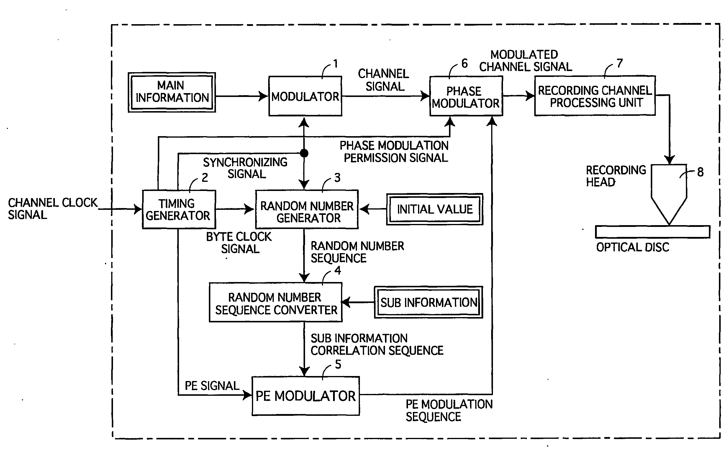
[0119] In Embodiment 3, a recording apparatus for the optical disc explained in Embodiments 1 and 2 will be described. FIG. 19 shows the internal structure of the recording apparatus in Embodiment 3. FIG. 20 is a timing chart for the recording apparatus. As shown in FIG. 19, the recording apparatus includes a modulator 1, a timing generator 2, a random number generator 3, a random number sequence converter 4, a PE modulator 5, a phase modulator 6, a recording channel processing unit 7, and a recording head 8.

Internal Structure of Recording Apparatus

[0120] The modulator 1 receives the data field data in units of 8 bits, performs the 8 / 16 modulation onto the received data to obtain 16-bit code words, and performs the NRZI conversion to the 16-bit code words to generate channel codes. The modulator 1 generates a channel signal by corresponding each of the generated channel codes to the clock pulse, then outputs to the generated channel signal to the phase modulator. When generating ...


PUM

PropertyMeasurementUnit
lengthaaaaaaaaaa
time periodaaaaaaaaaa
lengthsaaaaaaaaaa

Abstract

An optical disc having a plurality of sectors, each of which includes a plurality of frames. Sub information bit value “0” or “1” is assigned to the plurality of frames constituting a sector, excluding the first and last frames. Edge positions are displaced so that leading / lagging errors appear in accordance with a certain rule when data fields of the frames to which sub information bit value “1” is assigned are read. Edge positions are displaced so that leading / lagging errors appear in accordance with a reversed rule of the certain rule when data fields of the frames to which sub information bit value “0” is assigned are read.

Description

TECHNICAL FIELD [0001] The present invention relates to an optical disc such as DVD, a recording apparatus, and a reproduction apparatus, and relates to improvement in a technique for preventing copyright-protected data recorded on the optical disc from being used by an unauthorized party. BACKGROUND ART [0002] The traders of DVDs containing digital contents such as movies are on their guard against distribution or sale of pirated discs produced by unauthorized parties. Such pirated discs are produced with the use of two driving apparatuses. More specifically, a DVD containing a digital content is inserted into one driving apparatus, and an optical disc is inserted into the other. While the first driving apparatus obtains a read signal by reading the digital content from the DVD and converts the read signal into digital data, the second driving apparatus generates a write signal in accordance with the digital data, and writes a copy of the digital content onto the optical disc in ac...

Claims


Application Information

Patent Timeline
Patent Type & Authority Applications(United States)
IPC IPC(8): G11B5/09G11B7/24G11B7/26G11B7/007G11B7/013G11B7/24085G11B20/00G11B27/30
CPCG11B7/007G11B7/00745G11B7/24085G11B20/00086G11B20/0021G11B20/00268G11B2220/2562G11B20/00586G11B20/00594G11B20/0071G11B20/00768G11B20/10G11B27/3027G11B20/00376
Inventor NAGAI, TAKAHIROISHIHARA, HIDESHIYUMIBA, TAKASHITAKAHASHI, RIESHOJI, MAMORUYAMAGUCHI, HIROYUKIMIYASHITA, HARUMITSU
Owner PANASONIC CORP
Learn More