
Fouling and corrosion detector for process control industries

a technology for process control and detectors, applied in the direction of vibration measurement in solids, material analysis through optical means, instruments, etc., can solve the problems of corrosive properties, difficult detection, and common failure of heat exchangers

Active Publication Date: 2006-02-23
ROSEMOUNT INC
View PDF54 Cites 61 Cited by
  • Summary
  • Abstract
  • Description
  • Claims
  • Application Information

AI Technical Summary

Benefits of technology

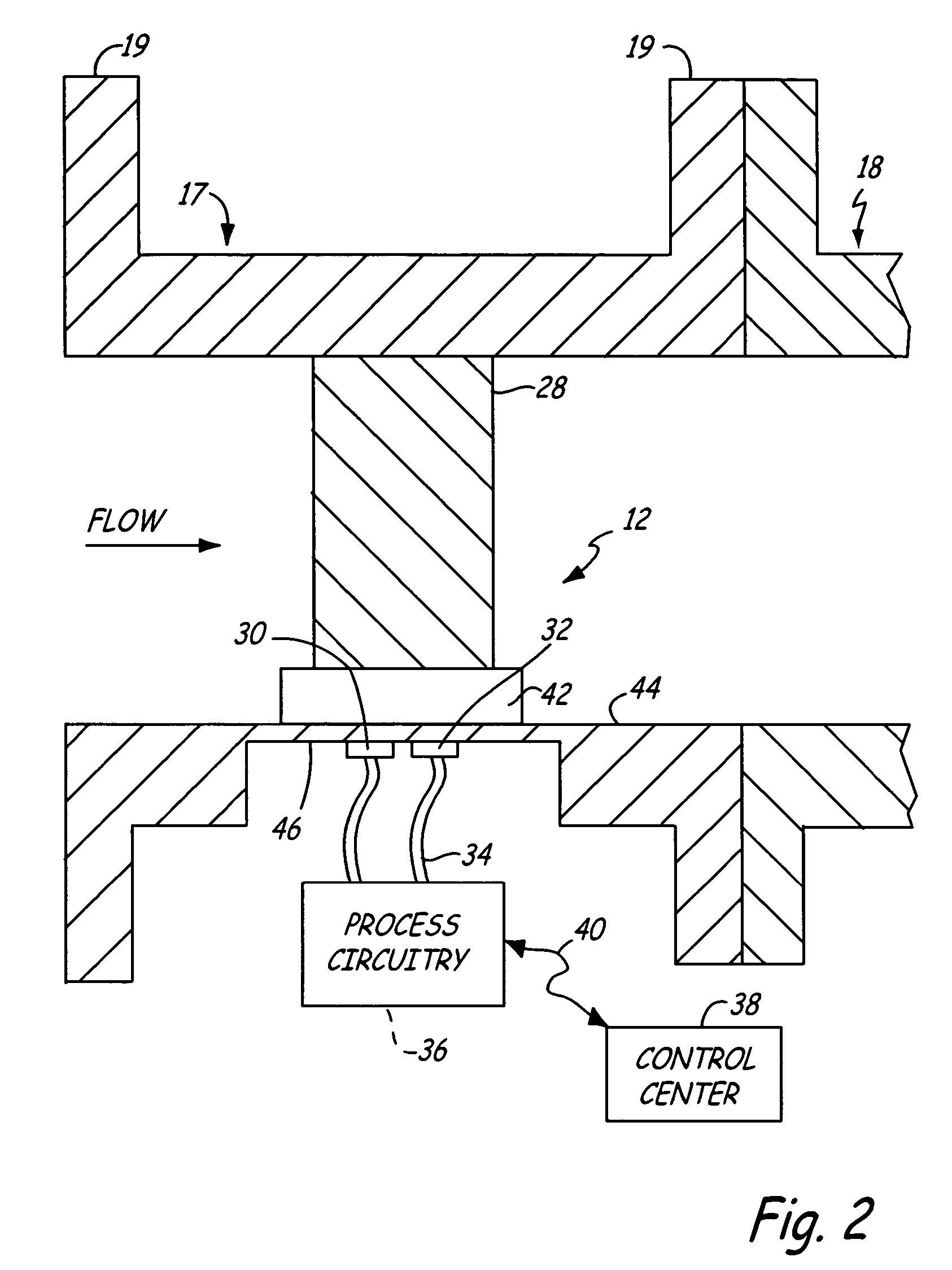
[0038] A powerful advantage of the present invention over prior art detectors is that the resonant frequency of the body 28 can be monitored to determine, not only whether corrosion or fouling is occurring, but also what type of build up is occurring (viscous or granular).

Problems solved by technology

Fouling is a common source of failure in heat exchangers, and can be difficult to detect.
In some embodiments, the fluid may be steam, or high or low temperature process materials, which may have corrosive properties.
Depending on the material used, the circulating fluid that passes through the exchanger may cause corrosion or may contain solids that can plug or coat the exchanger, thereby reducing the efficiency of the heat exchange process.
In general, corrosion and fouling may cause significant problems in an exchanger in an industrial process.
For example, if a heat exchanger becomes plugged due to fouling or if it fails due to corrosion (such as because seals become corroded and pressure is lost), process fluid fails to circulate through the exchanger core and the efficiency of the heat exchange may be compromised.
Additionally, if the exchanger core is used to deliver heat to a process or to remove heat from a process and the exchanger becomes plugged, the process may not reach the desired temperature.
Additionally, the process material that exchanges heat with the fluid in the exchanger core may foul or corrode the core from the outside, rendering the exchanger core inefficient.
If an exchanger core fails during operation, not only is the system shut down, but the batch may need to be discarded.
In the process industry, unplanned plant downtime can be very expensive due both to loss of production and to the cost of shutdown / start up.
The events that lead to unplanned plant downtime can also result in safety issues, environmental issues, and defective products.

Method used


Image

  • Fouling and corrosion detector for process control industries
  • Fouling and corrosion detector for process control industries
  • Fouling and corrosion detector for process control industries

Examples


Embodiment Construction

[0017] Generally, the present invention relates to a device that can be inserted in a process flow, preferably upstream from process elements, and that can be used to predict downstream fouling and corrosion conditions based on a resonant frequency of the device. The present invention also relates to techniques for predicting fouling and corrosion (or plugging) of process components based on a frequency response of a device positioned upstream from the process components.

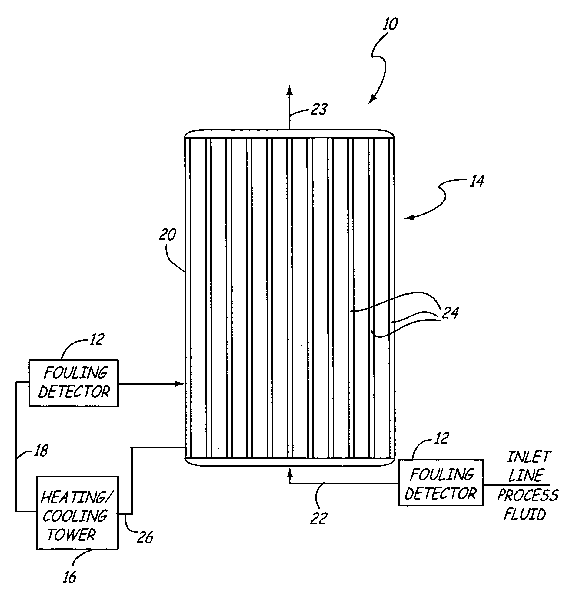
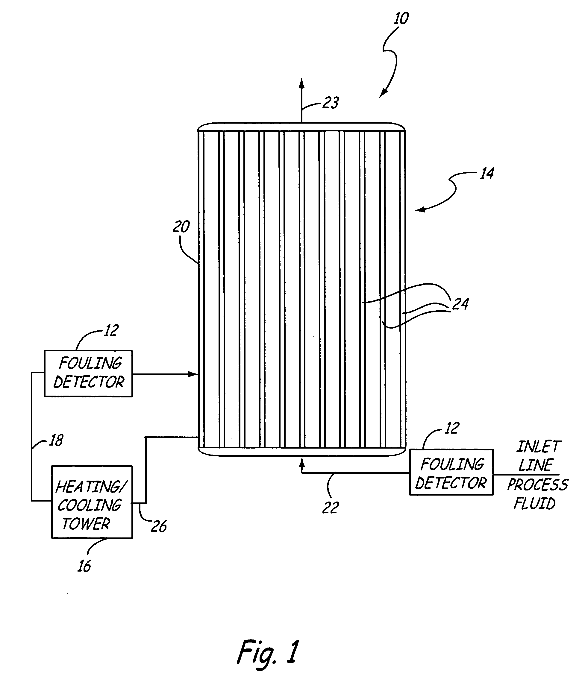
[0018]FIG. 1 shows a simplified block diagram of a of an industrial process 10, including fouling detectors 12 and a heat exchanger 14. The heat exchange system includes a fouling detector 12 positioned upstream from a heat exchanger 14, which is in turn coupled to a recycling tower 16 according to an embodiment of the present invention. Many components of the heat exchange system, which are conventional in design and not part of the present invention, have been omitted or simplified, including many elements of the...


PUM

PropertyMeasurementUnit
corrosionaaaaaaaaaa
frequency responseaaaaaaaaaa
damping coefficientaaaaaaaaaa

Abstract

A method for inferring possible or impending corrosion or fouling of process elements from fluid flowing in a pipe of an industrial process is described. A frequency response of a body is measured. The measured frequency response is compared against a stored value. Corrosion or fouling of the process elements is identified based upon the comparison between the measured frequency response and the stored value.

Description

BACKGROUND OF THE INVENTION [0001] The present invention generally relates to a fouling and corrosion detector for industrial processes, and more particularly, to a field-mounted detector for predicting fouling and corrosion of process elements in an industrial process. [0002] Generally, the term “fouling” refers to a build up of surface agents on a surface. Fouling is a common source of failure in heat exchangers, and can be difficult to detect. Heat exchangers are devices that facilitate, for example, the transfer of heat between a process and a fluid circulating within the exchanger. Heat exchangers are used in a number of industrial systems, including reactors, boilers and the like. [0003] Facilitating this thermal exchange is an exchanger core comprised of one or more tubes through which a fluid is continually circulated. As used herein, the term “fluid” refers to a process material in liquid or gaseous state. The fluid is circulated through the exchanger core. In some embodime...

Claims


Application Information

Patent Timeline
Patent Type & Authority Applications(United States)
IPC IPC(8): G01N17/04G01H11/08G01H13/00
CPCG01H3/12G01H13/00G01N17/008G01N29/4427G01N29/12G01N29/222G01N29/348G01N17/04
Inventor BROWN, GREGORY C.
Owner ROSEMOUNT INC
Learn More