
Apparatus and method for joint and time delayed measurements of components of conjugated quadratures of fields of reflected/scattered and transmitted/scattered beams by an object in interferometry

a technology of conjugated quadratures and interferometers, applied in the field of interferometry and interferometric measurements of properties of objects, can solve the problems of not teaching the practice of homodyne interferometry and the homodyne detection method does not make joint, so as to reduce the sensitivity to overlay errors, reduce vibration sensitivity, and fast scan rate

Inactive Publication Date: 2006-02-16
ZETETIC INST
View PDF69 Cites 18 Cited by
  • Summary
  • Abstract
  • Description
  • Claims
  • Application Information

AI Technical Summary

Benefits of technology

[0026] The conjugated quadratures of fields obtained jointly or substantially jointly and non-jointly with respect to time when operating in the scanning mode and using the homodyne detection methods have reduced sensitivity to pinhole-to-pinhole variations in properties of a conjugate set of pinholes used in a confocal microscopy system and reduced sensitivity to pixel-to-pixel variation of properties within a set of conjugate pixels of a multipixel detector in a confocal and in a non-confocal microscopy system. The conjugated quadratures of fields obtained jointly or substantially jointly and non-jointly with respect to time when operating in the scanning mode and using the homodyne detection methods have reduced sensitivity to pulse to pulse variations of a pulsed input beam to an interferometer system used in generating the conjugated quadratures of fields and reduced sensitivity to vibrations and to a relative motion of a substrate being imaged during the joint or substantially joint and non-joint acquisition of the conjugated quadratures of fields. The reduced sensitivity is with respect to the corresponding sensitivity of conjugated quadratures of fields obtained when using a single-homodyne detection mode in either a scanning or non-scanning mode. In microscopy applications, components of conjugated quadratures of fields are obtained for each spot in and / or on a substrate that is imaged.
[0043] Another advantage of at least one embodiment of the present invention is that the common mode phase of corresponding reference and measurement beam components of an input beam to an interferometer does not affect values of measured conjugated quadratures when using the homodyne detection methods.

Problems solved by technology

However, the prior art does not teach the practice of acquisition of the respective at least four electrical interference signal values in interferometric far-field, evanescent-field, and near-field confocal and non-confocal microscopy when operating in a relatively fast scanning mode wherein each electrical interference signal value of the at least four electrical interference signal values corresponds to the same or substantially the same respective spot on or in a substrate and contains information that can be used for determination of joint or substantially joint and non-joint measurements of components of conjugated quadratures of fields reflected / scattered or transmitted / scattered by the respective spot in both spatial and temporal coordinates.
However, the prior art does not teach the practice of homodyne interferometry wherein joint or substantially joint measurements in both spatial and temporal coordinates are made of conjugated quadratures of fields of beams reflected from a measurement object in single- or multiple-frequency linear and angular displacement interferometers.
Accordingly, the double homodyne detection method does not make joint or substantially joint determinations of conjugated quadratures of fields wherein each electrical interference value contains information simultaneously or substantially simultaneously about each of two orthogonal components of the conjugated quadratures.

Method used


Image

  • Apparatus and method for joint and time delayed measurements of components of conjugated quadratures of fields of reflected/scattered and transmitted/scattered beams by an object in interferometry
  • Apparatus and method for joint and time delayed measurements of components of conjugated quadratures of fields of reflected/scattered and transmitted/scattered beams by an object in interferometry
  • Apparatus and method for joint and time delayed measurements of components of conjugated quadratures of fields of reflected/scattered and transmitted/scattered beams by an object in interferometry

Examples


Embodiment Construction

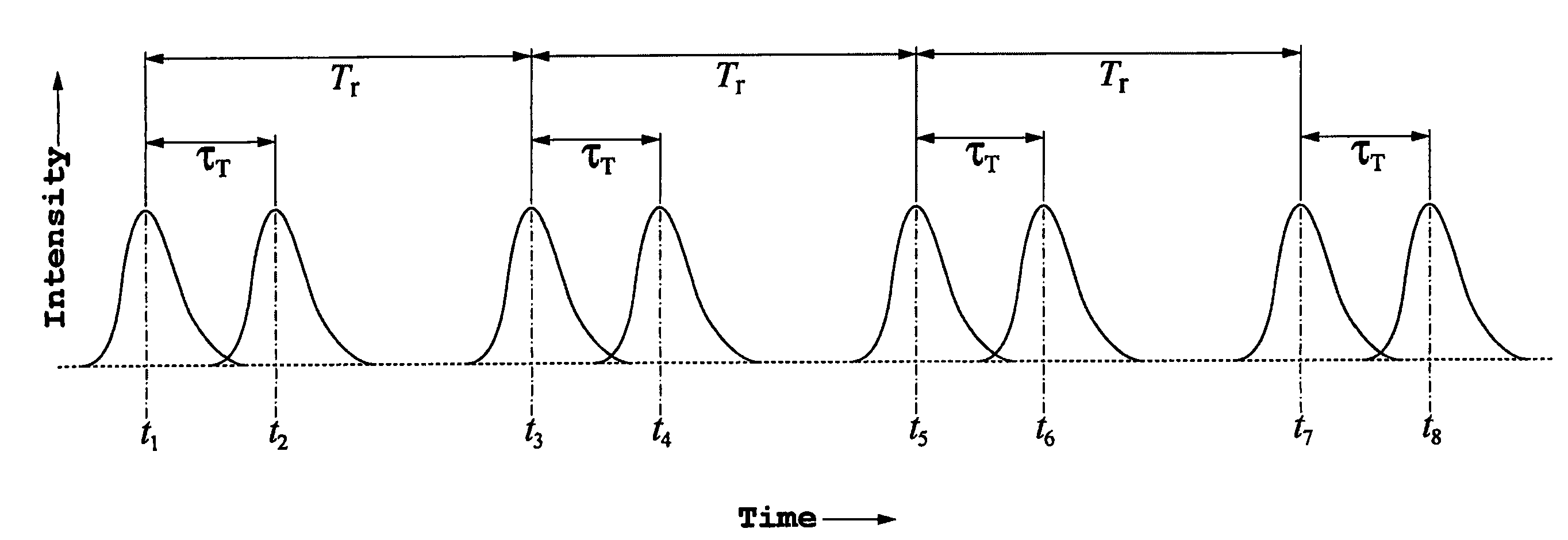
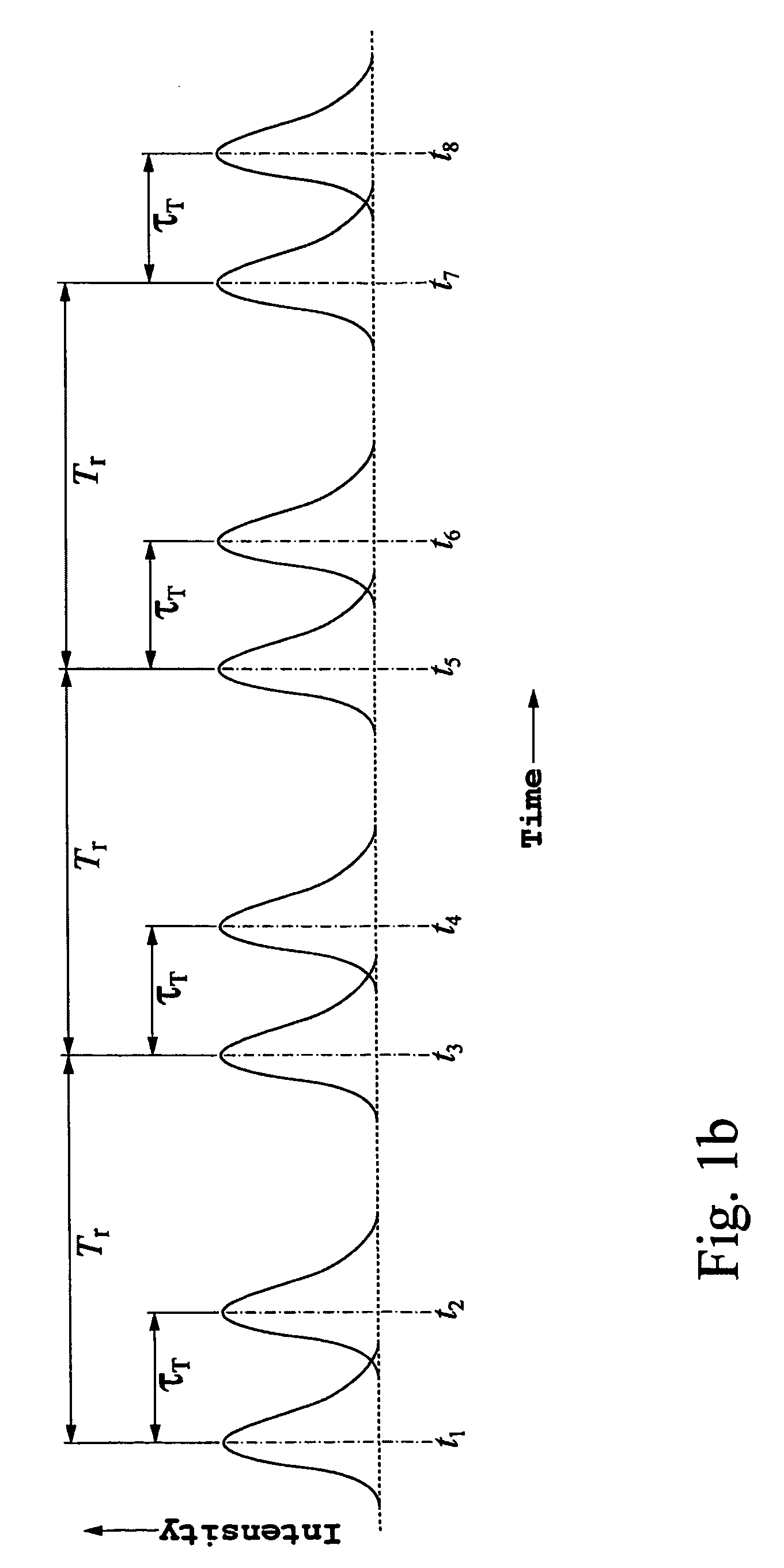
[0065] High speed, high resolution imaging with high signal-to-noise ratios is required for example in the metrology and inspection of masks and wafers in microlithography. Techniques for obtaining high resolution imaging with high signal-to-noise ratios are interferometric far-field, evanescent-field, and near-field confocal and non-confocal microscopy. However, the high signal-to-noise ratios with the high resolution imaging generally limits data rates in part by the necessity to acquire conjugated quadratures of fields of a reflected / scattered beam or of a transmitted / scattered beam for each spot in and / on a substrate being imaged. The determination of N′ conjugated quadratures requires the measurement of at least a harmonic multiple N′ electrical interference signal values for each spot in and / or on the substrate being imaged. Acquisition of the at least 4 N′ interference signal values for the each spots places tight restrictions on how large a rate of scan can be employed in ge...


PUM


Abstract

A method of interferometrically obtaining measurements for properties associated with a spot on or in an object, the method involving: receiving a sequence of M optical pulses separated in time; from each pulse in the sequence of M optical pulses, generating an n-tuplet of measurement pulses, and an n-tuplet of reference pulses, wherein each measurement pulse has a corresponding reference pulse aligned with it in time; from each pulse of each n-tuplet of reference pulses for the sequence of M optical pulses, generating a reference beam; from each pulse of each n-tuplet of measurement pulses for the sequence of M optical pulses, (a) generating a measurement beam; (b) directing the measurement beam onto the spot to thereby produce a return measurement beam from the spot; and (c) combining the return measurement beam with the corresponding reference beam that was derived from the reference pulse corresponding to that measurement pulse to generate an interference beam, wherein the sequence of M n-tuplets of measurement pulses forms n interleaved sequences of M measurement pulses, and wherein the method further involves, for each of the n interleaved sequences of M measurement pulses, introducing a combination of phase shifts between the measurement beams and corresponding reference beams.

Description

[0001] This application claims the benefit of U.S. Provisional Application No. 60 / 602,046 filed Aug. 16, 2004.TECHNICAL FIELD [0002] This invention relates to interferometry and interferometric measurements of properties of an object. BACKGROUND OF THE INVENTION Related Disclosures [0003] The following applications are related to the present application: U.S. Pat. No. 6,552,852, issued Apr. 22, 2003, entitled “Catoptric and Catadioptric Imaging Systems” (ZI-38); U.S. Ser. No. 60 / 447,254, filed Feb. 13, 2003, and U.S. Ser. No. 10 / 778,371, filed Feb. 13, 2004, both of which are entitled “Transverse Differential Interferometric Confocal Microscopy,” (ZI-40); U.S. Ser. No. 60 / 448,360, filed Feb. 19, 2003, and U.S. Ser. No. 10 / 782,057, filed Feb. 19, 2004, both of which are entitled “Longitudinal Differential Interferometric Confocal Microscopy For Surface Profiling,” (ZI-41); U.S. Ser. No. 60 / 448,250, filed Feb. 19, 2003, and U.S. Ser. No. 10 / 782,058, filed Feb. 19, 2004, both of which ...

Claims


Application Information

Patent Timeline
IPC IPC(8): G01B9/02
CPCG01B9/02079G01B9/02014G01B2290/70G01B9/02068G01B9/02022
Inventor HILL, HENRY ALLEN
Owner ZETETIC INST
Learn More