
Printing apparatus, printing system, printing method, and program

a printing system and printing apparatus technology, applied in the direction of printing, other printing apparatus, etc., can solve the problems of inability to print variable data, significant efficiency drop, and increase in unit printing cost, and achieve the effect of high speed and high printing speed

Inactive Publication Date: 2006-02-16
COPYER
View PDF12 Cites 21 Cited by
  • Summary
  • Abstract
  • Description
  • Claims
  • Application Information

AI Technical Summary

Benefits of technology

[0035] With this invention, a plurality of same color print heads capable of ejecting the same color ink are controlled based on the same print data, and the drive timings at which to drive these same color print heads are so set that the image portions printed by the same color print heads will overlap each other. This arrangement allows high-density images to be formed by the ink dots of the same color overlapping each other.
[0036] Further, the drive timings for the plurality of the same color print heads can reliably be set according to a synchronization signal corresponding to the transport speed of the print medium and the positional relation of the plurality of the same color print heads in the transport direction of the print medium.
[0037] Further, by providing a set of the same color print heads for each of the plurality of color inks, it is possible to print not only high-density single-color images but also high-density color images.
[0038] Further, by controlling the plurality of the same color print heads according to the print data which is allocated in units of raster columns to these same color print heads and by setting the drive timings for these same color print heads such that the image portions printed by them will supplement each other to complete an image, the image can be printed at high speed. Also by providing a set of the same color print heads for each of the color inks, it is possible to print at high speed not only single-color images but also color images.

Problems solved by technology

Thus, if these printing machines are used for many-kinds-in-small-lots printing, a unit printing cost increases.
Further, inserting a small-lot print job in a large-lot print job in a printing operation using these printing machines will result in a significant fall in efficiency.
Further, since the content of printing is fixed by the printing plate, it is impossible to print variable data.
However, although the ink jet printing apparatus can produce a satisfactory image quality when a print medium is dedicated paper such as coated paper, if such dedicated paper cannot be used, a required level of image quality may not necessarily be obtained.
For example, when an ink jet printing apparatus is employed in the form printing and conventional offset printing paper is used, there is a possibility of the print density becoming insufficient.
Further, if the ink jet printing apparatus is employed in a corrugated cardboard printing, since ink dedicated for the ink jet printing apparatus soaks into cardboard quickly, the print density may become undesirably low.
In the wall paper printing, although a light tone is desired, it is currently difficult to realize a desired color reproduction capability with the ink jet printing apparatus.

Method used


Image

  • Printing apparatus, printing system, printing method, and program
  • Printing apparatus, printing system, printing method, and program
  • Printing apparatus, printing system, printing method, and program

Examples


first embodiment

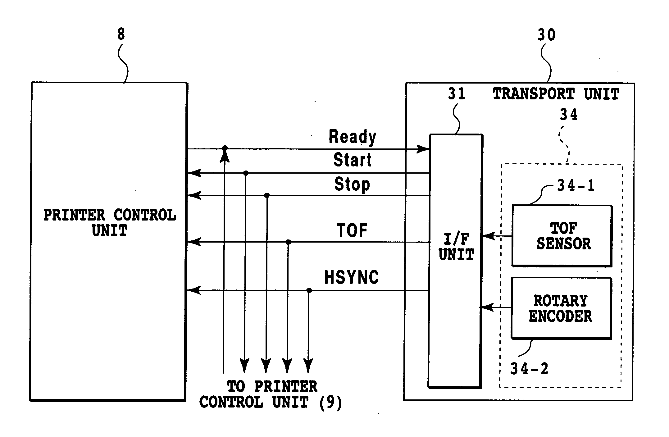
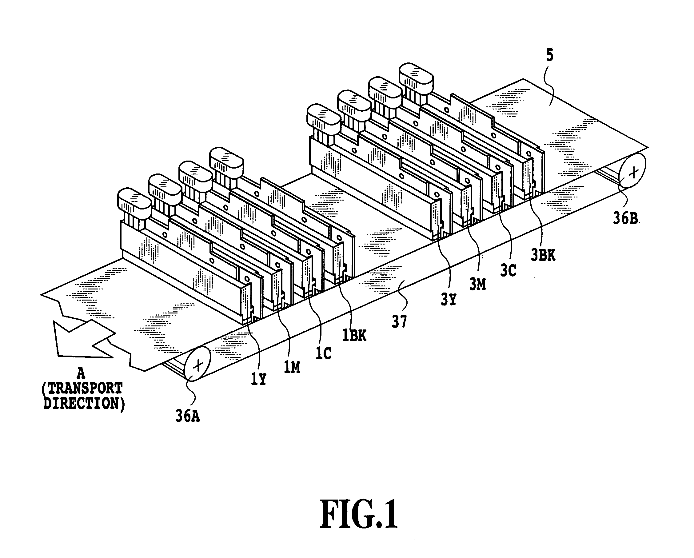
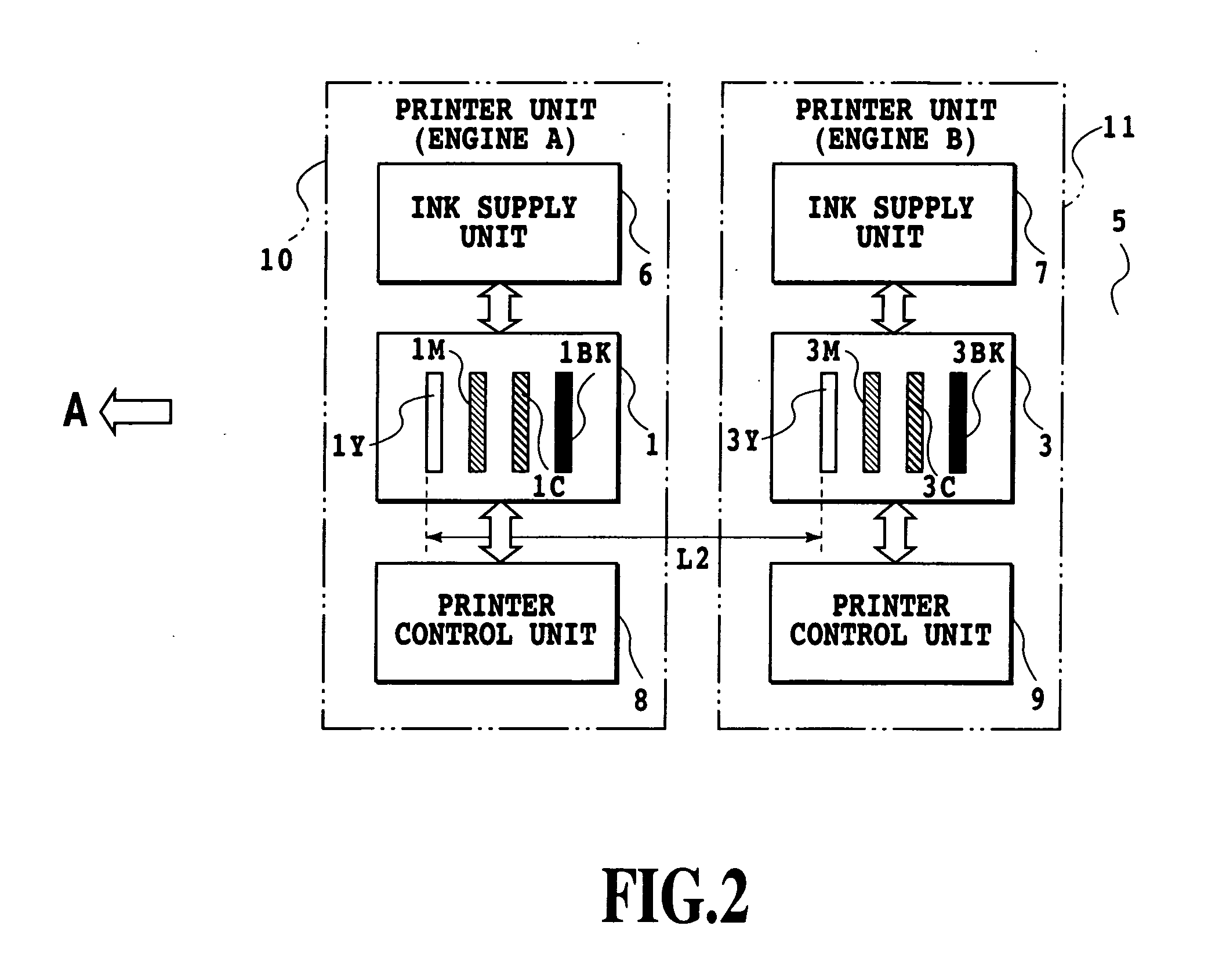
[0059]FIG. 1 is an outline perspective view showing an essential portion of the printing apparatus of this embodiment. FIG. 2 is a block diagram of an image printing unit in the printing apparatus of FIG. 1. FIG. 3 is a block configuration diagram showing a control system of the printing apparatus of FIG. 1. The printing apparatus of this embodiment, as shown in FIG. 3, has two independent printer units (also referred to as “engine A, B”) 10, 11 and a transport unit 30 and, together with a host device in the form of a personal computer (also referred to as a “host PC”), forms a printer composite system (printing system).

[0060] The printer unit 10 includes a head unit 1, an ink supply unit 6 and a printer control unit 8. The head unit 1 has four print heads (also referred to as line heads) 1Y, 1M, 1C, 1Bk removably mounted thereon and extending in a direction crossing a transport direction A of a print medium 5 (in this example, a direction perpendicular to the transport direction A...

second embodiment

[0122]FIG. 13 is a block diagram of an image printing unit in a printing apparatus as a second embodiment of this invention.

[0123] In this embodiment, the head units 1, 3 in the printer units 10, 11 are each provided with four black ink print heads (1Bk-1, 1Bk-2, 1Bk-3, 1Bk-4; and 3Bk-1, 3Bk-2, 3Bk-3, 3Bk-4). The ink supply units 6, 7 are dedicated for black ink. Other configurations are similar to those of the first embodiment.

[0124] In the high-speed print mode, bit map data for black ink (B data) is divided into single columns of raster data, each extending along the nozzle column (raster division), and each raster data column is distributed among the total of eight print heads. This arrangement can make the printing speed four times faster than that of the high-speed print mode of the first embodiment in which the print data is divided and allocated to two print heads, (4V). During the high-density print mode, the print data is distributed so that two dots are overlappingly pr...


PUM


Abstract

This invention allows for a high-density image printing by using ink jet print heads capable of ejecting ink. For this purpose, a plurality of same color print heads capable of ejecting the same color ink are controlled according to the same print data. Drive timings for the same color print heads are so set that the image portions printed by these same color print heads overlap each other.

Description

[0001] The application claims priority from Japanese Patent Application No. 2004-231100 filed on Aug. 6, 2004, which is incorporated herein by reference. BACKGROUND OF THE INVENTION [0002] 1. Field of the Invention [0003] The present invention relates to a printing apparatus, a printing system, a printing method and a program to print images using a plurality of print heads capable of ejecting ink. [0004] 2. Description of the Related Art [0005] Printing very few kinds of materials in large quantities, as in pamphlet printing and corrugated cardboard printing, has conventionally been performed using an offset printing machine and a flexographic printing machine. These printing machines (printing apparatus) require a printing plate for each print job and thus the printing plate must be replaced and ink cleaning done every time the print job is changed. Thus, if these printing machines are used for many-kinds-in-small-lots printing, a unit printing cost increases. Further, inserting a...

Claims


Application Information

Patent Timeline
Patent Type & Authority Applications(United States)
IPC IPC(8): B41J29/38
CPCB41J2/515
Inventor AOKI, AKIO
Owner COPYER
Learn More