
Highlevel active pen matrix

a pen matrix and high-level technology, applied in the field of graphical user interface control apparatus and methods, can solve the problems of limited use of stylus in graphical user interface, inability to use or be desirable, and limited current system

Inactive Publication Date: 2006-02-16
MICROSOFT TECH LICENSING LLC
View PDF13 Cites 109 Cited by
  • Summary
  • Abstract
  • Description
  • Claims
  • Application Information

AI Technical Summary

Benefits of technology

Enables users to perform all operations of a mouse-type device using a stylus, enhancing usability and functionality in stylus-based computing environments, allowing for writing, editing, and manipulating objects directly on the display surface.

Problems solved by technology

In some environments, a mouse is not usable or desirable.
While a stylus attempts to provide pad and paper-like feel to a computing environment, current systems are limited.
For example, the use of a stylus in a graphical user interface is limited to tapping on various items for selection.
Further, in stylus-based input environments, a user is continually forced to select tools or operations from a remote tool bar, generally on a top or bottom of a screen.
In short, requiring a user to tell the computer, for every new input, what a user wants to do makes stylus-based computing difficult for the average user.

Method used


Image

  • Highlevel active pen matrix
  • Highlevel active pen matrix
  • Highlevel active pen matrix

Examples


Embodiment Construction

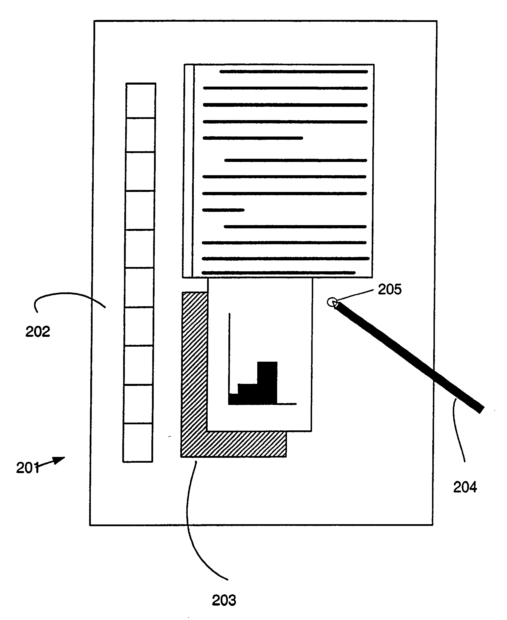
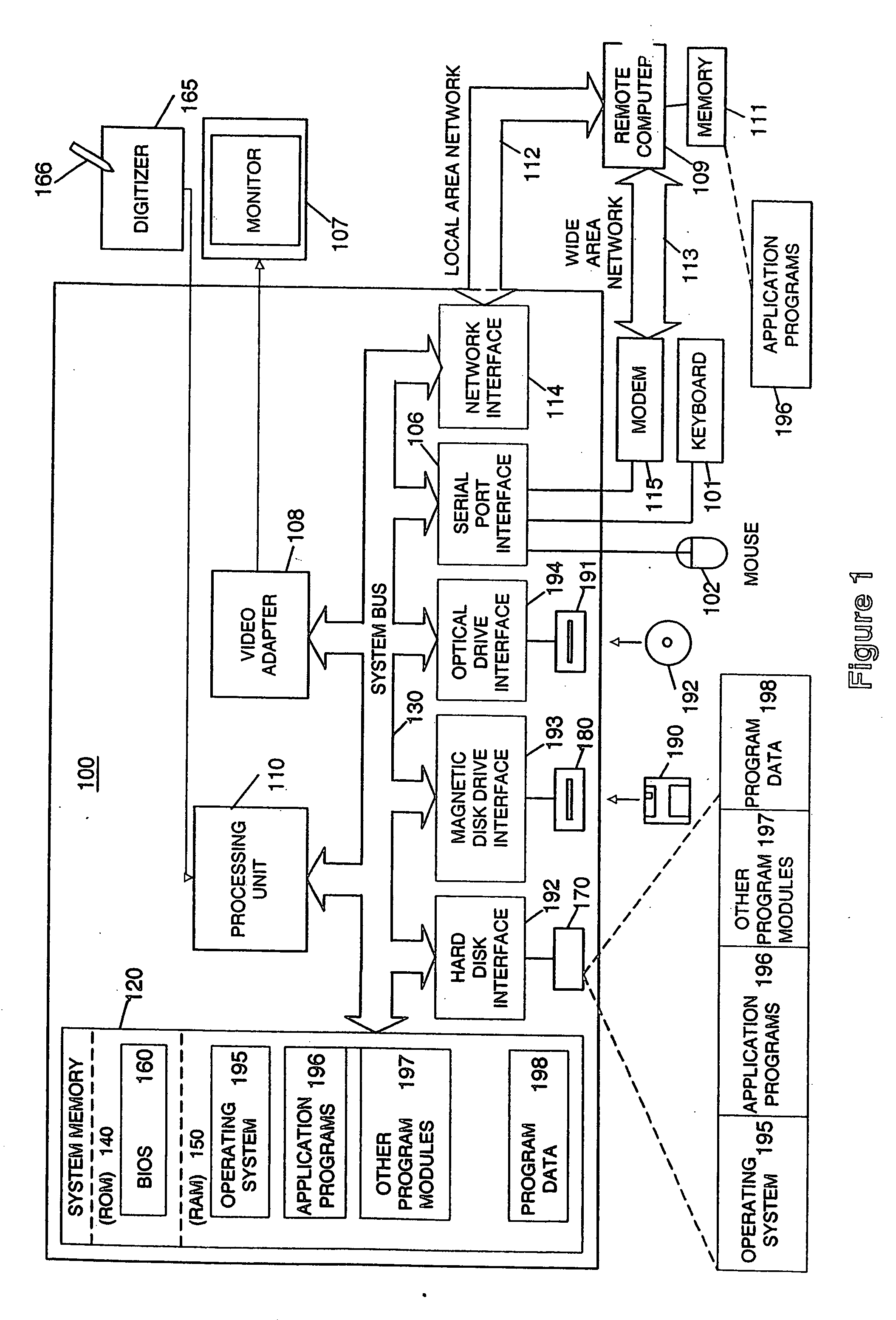
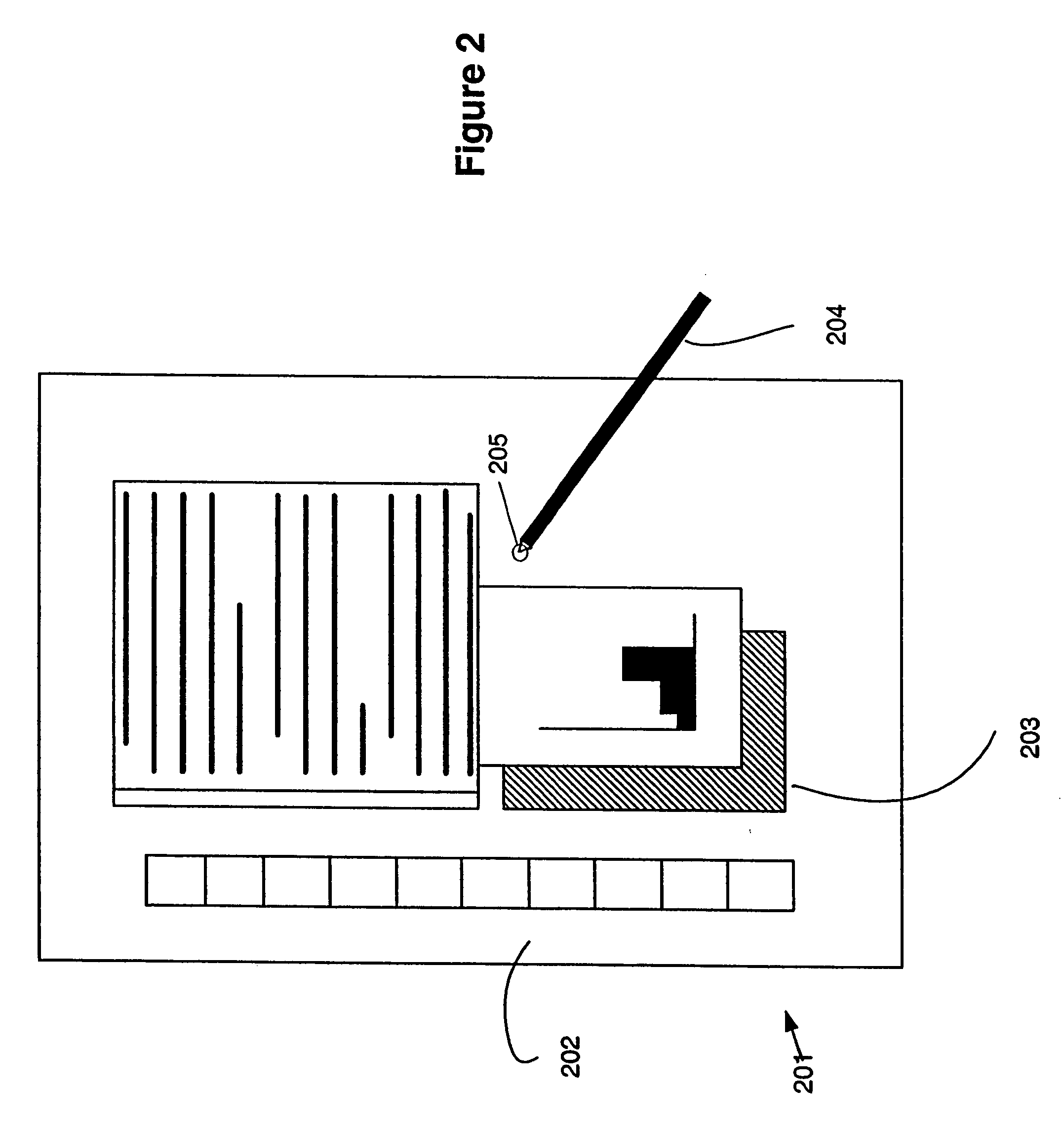
[0018] The present invention may be more readily described with reference to FIGS. 1-7. FIG. 1 illustrates a schematic diagram of a conventional general-purpose digital computing environment that can be used to implement various aspects of the present invention. In FIG. 1, a computer 100 includes a processing unit 110, a system memory 120, and a system bus 130 that couples various system components including the system memory to the processing unit 110. The system bus 130 may be any of several types of bus structures including a memory bus or memory controller, a peripheral bus, and a local bus using any of a variety of bus architectures. The system memory 120 includes read only memory (ROM) 140 and random access memory (RAM) 150.

[0019] A basic input / output system 160 (BIOS), containing the basic routines that help to transfer information between elements within the computer 100, such as during start-up, is stored in the ROM 140. The computer 100 also includes a hard disk drive 170...


PUM


Abstract

The present invention relates to a system, method and medium for receiving and acting upon user input. In one embodiment, the user may only have access to a limited input device, like a stylus. Using the present invention, a user is provided with intuitive responses from the system based on inputs from the limited input device.

Description

CROSS-REFERENCE TO RELATED APPLICATIONS [0001] The present application is a continuation of U.S. patent application Ser. No. 10 / 993,357, filed Nov. 22, 2004 which is a continuation of U.S. patent application Ser. No. 09 / 736,170, filed Dec. 15, 2000, now issued as U.S. Pat. No. 6,897,853, which claims priority to U.S. Provisional Patent Application Ser. No. 60 / 247,400, filed Nov. 10, 2000, each of which is incorporated by reference herein as to its entirety.FIELD OF THE INVENTION [0002] Aspects of the present invention are directed generally to apparatus and methods for controlling a graphical user interface (GUI). More particularly, the present invention relates to receiving user input, determining based on the user input what the user wants to do, and performing a function related to the desired input. BACKGROUND OF THE INVENTION [0003] Typical computer systems, especially computer systems using graphical user interface (GUI) systems such as Microsoft WINDOWS, are optimized for acc...

Claims


Application Information

Patent Timeline
Patent Type & Authority Applications(United States)
IPC IPC(8): G09G5/00G06F3/041G06F1/16G06F3/023G06F3/038G06K9/62G06K9/68G10L15/26
CPCG06F1/1626G06F3/0238G06F3/038G06F3/0412G10L15/26G06F3/04886G06K9/6293G06F3/041G06F3/04883G06F18/256
Inventor KEELY, LEROY B.LUI, CHARLTON E.JONES, F. DAVIDCUKIERMAN, RYAN EDWARDCAZZANTI, SUSANNE ALYSIA CLARKIWEMA, MARIEKEJARRETT, ROBERT
Owner MICROSOFT TECH LICENSING LLC
Learn More