
Cutting tool wear sleeves and retention apparatuses

Inactive Publication Date: 2006-02-16
FREAR JOSEPH K
View PDF12 Cites 47 Cited by
  • Summary
  • Abstract
  • Description
  • Claims
  • Application Information

AI Technical Summary

Benefits of technology

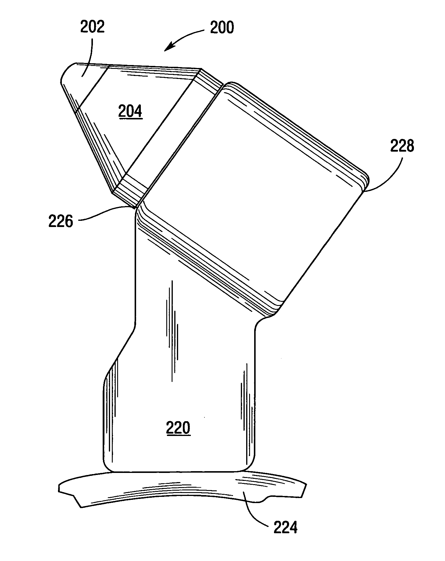
[0011] Another embodiment of the present invention comprises a cutting tool assembly that includes a support block that has a sleeve-receiving hole therethrough. The assembly further includes a cutting tool that has an elongated shank comprising a first shank portion that has a first diameter, a second shank portion that has a second diameter that is less than the first diameter of the first shank portion, and an end portion that has the first diameter. The end portion is oriented such that the second shank portion is between the first shank portion and the end portion. The assembly further in

Problems solved by technology

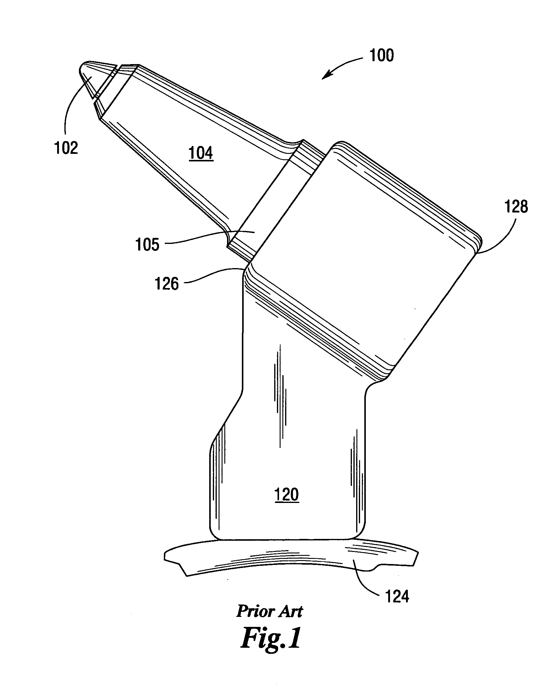
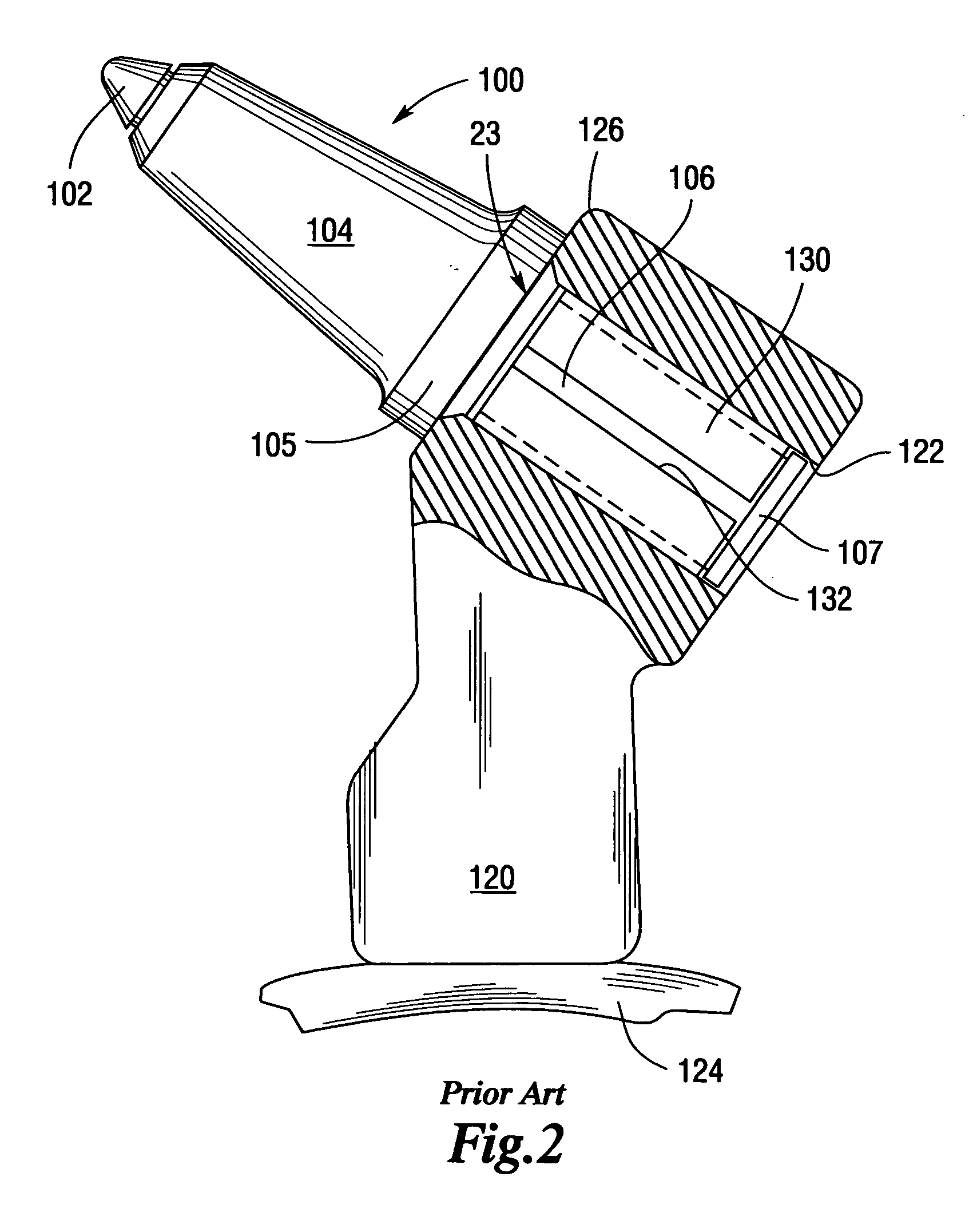
Such prior retention sleeve arrangements can be difficult to install.
Often times the installation takes place in cramped quarters further complicating the installation process and exposing the installer to injury should the hammer inadvertently miss the bit and strike the installer's other hand that is supporting the bit adjacent the hole opening.
Further, while being difficult to install, the retention forces (i.e., the amount of force required to press the sleeve and bit out of the hole in the support block) attained by such prior arrangements are not high (i.e., commonly on the order of 100 to 120 pounds).
Furthermore, when using many prior wear sleeve arrangements that are pressed fit into a bore in a support block, the diameter and the total roundness of the bore are critical.
If the diameter of the bore is too small, the sleeve could only be installed with great difficulty, if at all.
In extreme instances, a bore that was too small may actually result in the sleeve becoming deformed or otherwise damaged which could result in damage to the bit shank.
Such arrangements may also be difficult to remove.
Such processes can be expensive and time consuming.

Method used


Image

  • Cutting tool wear sleeves and retention apparatuses
  • Cutting tool wear sleeves and retention apparatuses
  • Cutting tool wear sleeves and retention apparatuses

Examples


example

[0089] Length of sleeve 250 (distance “L”): 1.000 inches;

[0090] Diameter “F” of sleeve-receiving hole 222 in support block 220: 1.510 inches and a circumference of 4.744 inches;

[0091] Diameter “A” of the elongated shank 208: 1.312 inches;

[0092] Diameter “E” of the retaining flange 210: 1.500 inches;

[0093] Outer diameter “H” of sleeve 250 (with ends butted): 1.540 inches;

[0094] Outer circumference (with ends butted): 4.838 inches;

[0095] Inner diameter “I” of sleeve 250 (with ends butted): 1.390 inches;

[0096] If provided—Space “K” between first and second ends 258, 260 (prior to insertion): 0.125 inches;

[0097] Number of first notches 266: three;

[0098] Length “M” of first notches 266: 0.550 inches;

[0099] Width “S” of first notches 266: 0.125 inches;

[0100] Number of second notches 270: three;

[0101] Length ““N”” of second notches 270: 0.550 inches;

[0102] Width “T” of second notches 270: 0.125 inches.

[0103] The foregoing dimensions are but one example of a retention sleeve e...


PUM


Abstract

Cutting tool assemblies and wear and retention sleeves. The assemblies may include a support block that has a sleeve-receiving hole therethrough and a cutting tool that has an elongated shank. Various configurations of sleeves are disclosed for supporting the elongated shank of the cutting bit in the support block. Such sleeve embodiments may be provided with a plurality of axially extending overlapping notches to establish segments of various degrees of interference fit between the sleeve and the support block when seated in the sleeve-receiving hole of the support block. Some sleeve embodiments are configured to permit the shank of a cutting bit to freely rotate therein. Other sleeve embodiments are configured to prevent rotation of the cutting bit shank when inserted therein.

Description

BACKGROUND [0001] 1. Field of the Invention [0002] Various embodiments of the subject invention relate to tool retainers and tool retainer systems and, more particularly, to wear and retention sleeves for supporting and retaining a cutting tool within a support member. [0003] 2. Description of the Invention Background [0004] Over the years, man has designed a variety of different tools for cutting materials. One such tool is employed in the mining of underground materials such as coal and the like. The tools, commonly referred to as “cutting bits”, are affixed to rotating cutting drums located on mining machines. As the cutting bits are advanced into the material to be mined, the cutting bits dislodge the material from the seam to enable it to be collected on a conveyor arrangement for removal from the mine. Each such cutting bits commonly has an elongated cylindrical shank portion that is received in a mounting block that is attached to the driven cutting drum. A replaceable cuttin...

Claims


Application Information

Patent Timeline
IPC IPC(8): E21C35/197
CPCE21C35/197
Inventor FREAR, JOSEPH K.
Owner FREAR JOSEPH K
Learn More