
Electric generator control method and apparatus, and vehicle equipped with such apparatus

a technology of electric generators and control methods, which is applied in the direction of electric generator control, machines/engines, cycles, etc., can solve the problems of limited driving conditions capable of achieving the benefits of increasing the acceleration capability of vehicles cannot be increased, so as to achieve the acceleration capability of vehicles can be increased, and the load due to electricity generation by electric generators can be further reduced.

Inactive Publication Date: 2006-02-16
HONDA MOTOR CO LTD
View PDF7 Cites 5 Cited by
  • Summary
  • Abstract
  • Description
  • Claims
  • Application Information

AI Technical Summary

Benefits of technology

The invention relates to an electric generator control apparatus for vehicles that adjusts the amount of electric power generated by an electric generator in response to the position of the throttle valve. The apparatus reduces the amount of electric power generated when the throttle valve is fully opened, which reduces the load on the engine and allows for a smoother acceleration of the vehicle. The amount of electric power generated is gradually reduced as the throttle valve is opened, and the apparatus is designed to minimize any adverse effects on the battery or other electric load. The invention also provides a method for controlling the electric generator control apparatus to further improve the acceleration capability of the vehicle.

Problems solved by technology

According to the conventional electric generator control apparatus of the reference, however, since the battery charging voltage switches from 14.5 V to 12.0 V when the throttle opening reaches a nearly fully opened value, the vehicle acceleration capability cannot be increased unless the throttle opening is brought to the nearly fully opened value.
Consequently, driving conditions capable of accomplishing the benefits of the increased vehicle acceleration capability are limited.

Method used


Image

  • Electric generator control method and apparatus, and vehicle equipped with such apparatus
  • Electric generator control method and apparatus, and vehicle equipped with such apparatus
  • Electric generator control method and apparatus, and vehicle equipped with such apparatus

Examples


Embodiment Construction

[0032] A selected illustrative embodiment of the present invention will be described below, with reference to the drawings. In the following description, relative terms such as front, rear, right and left refer to those directions considered from the vantage point of a driver seated on the vehicle and facing forward.

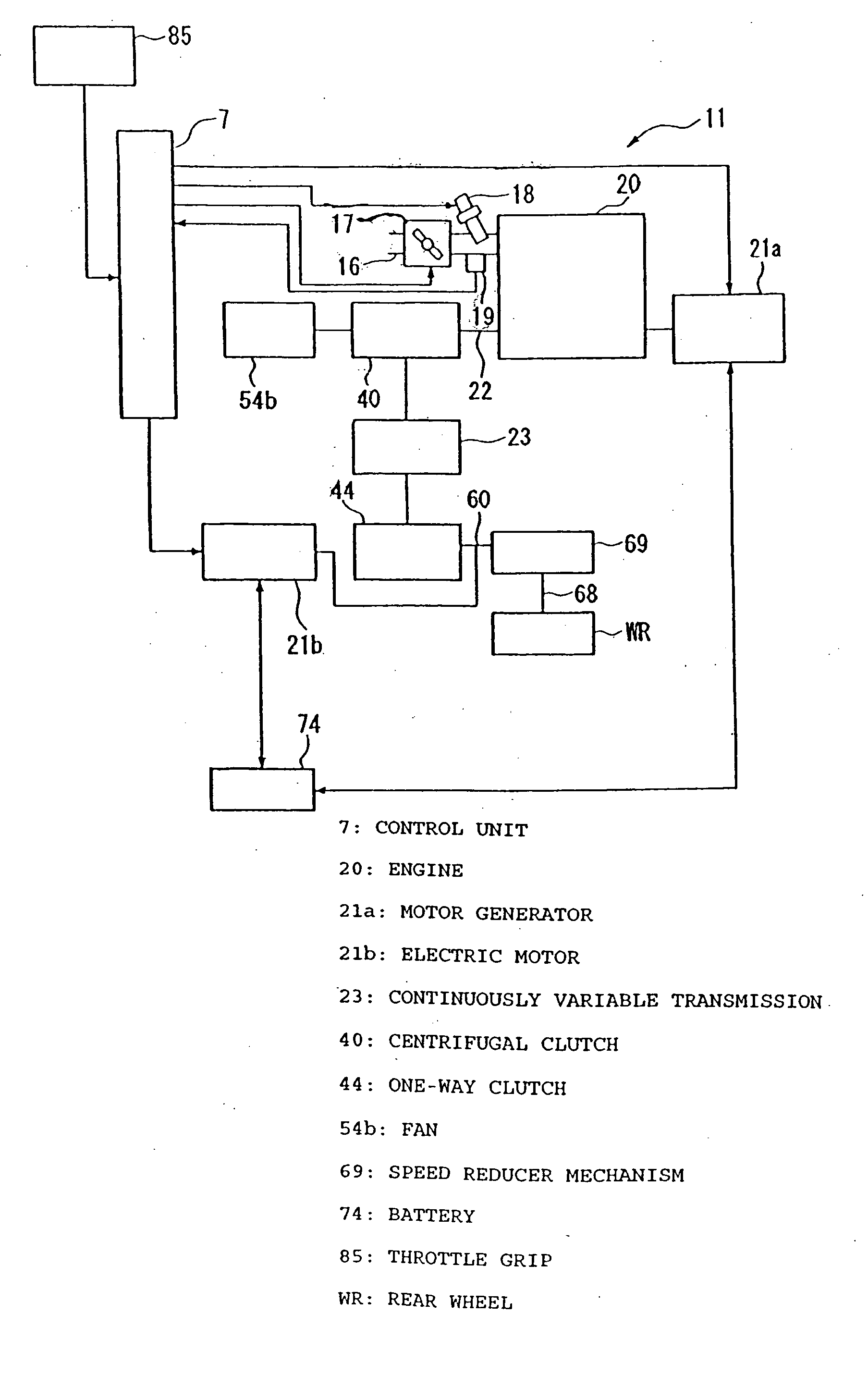
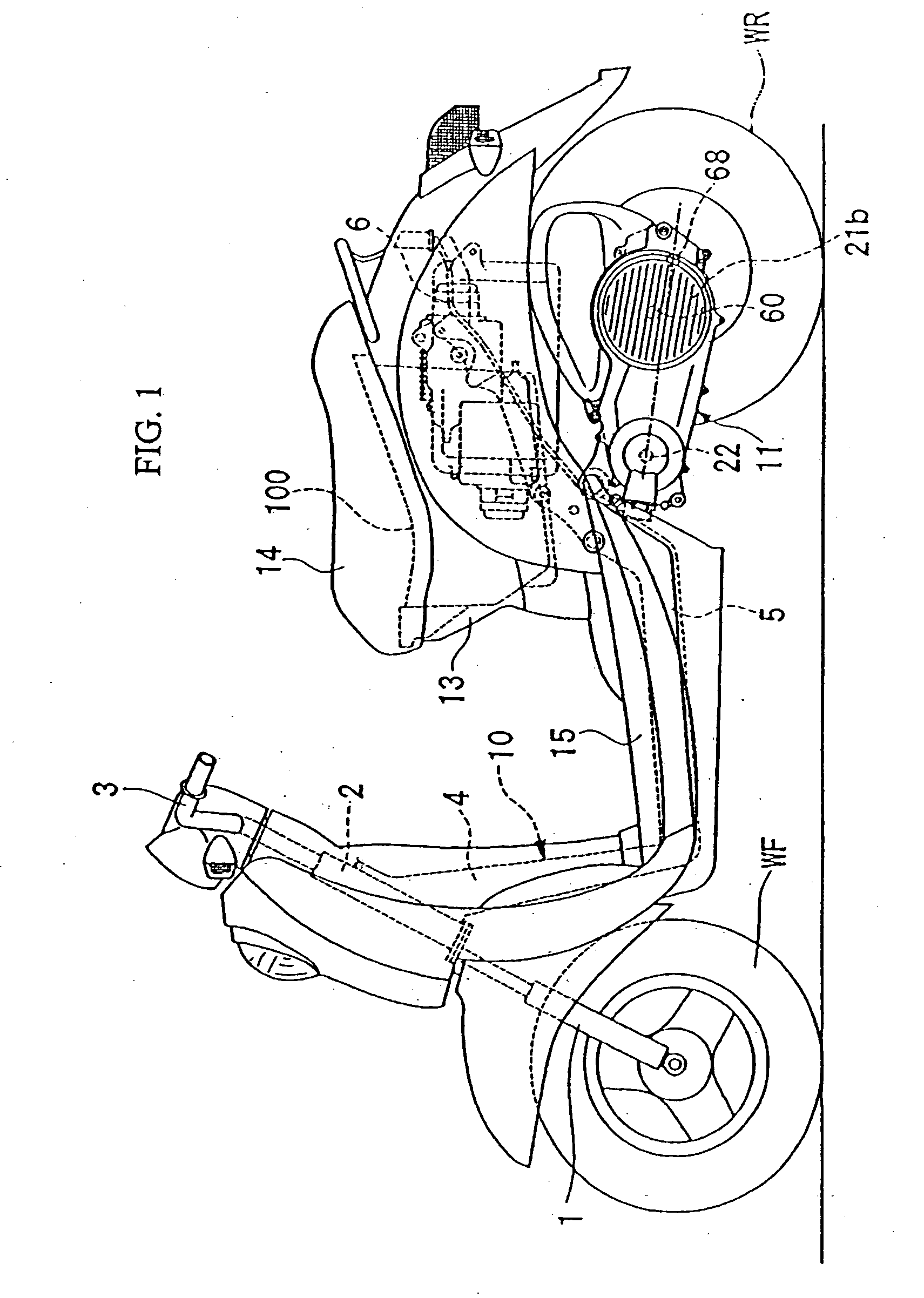
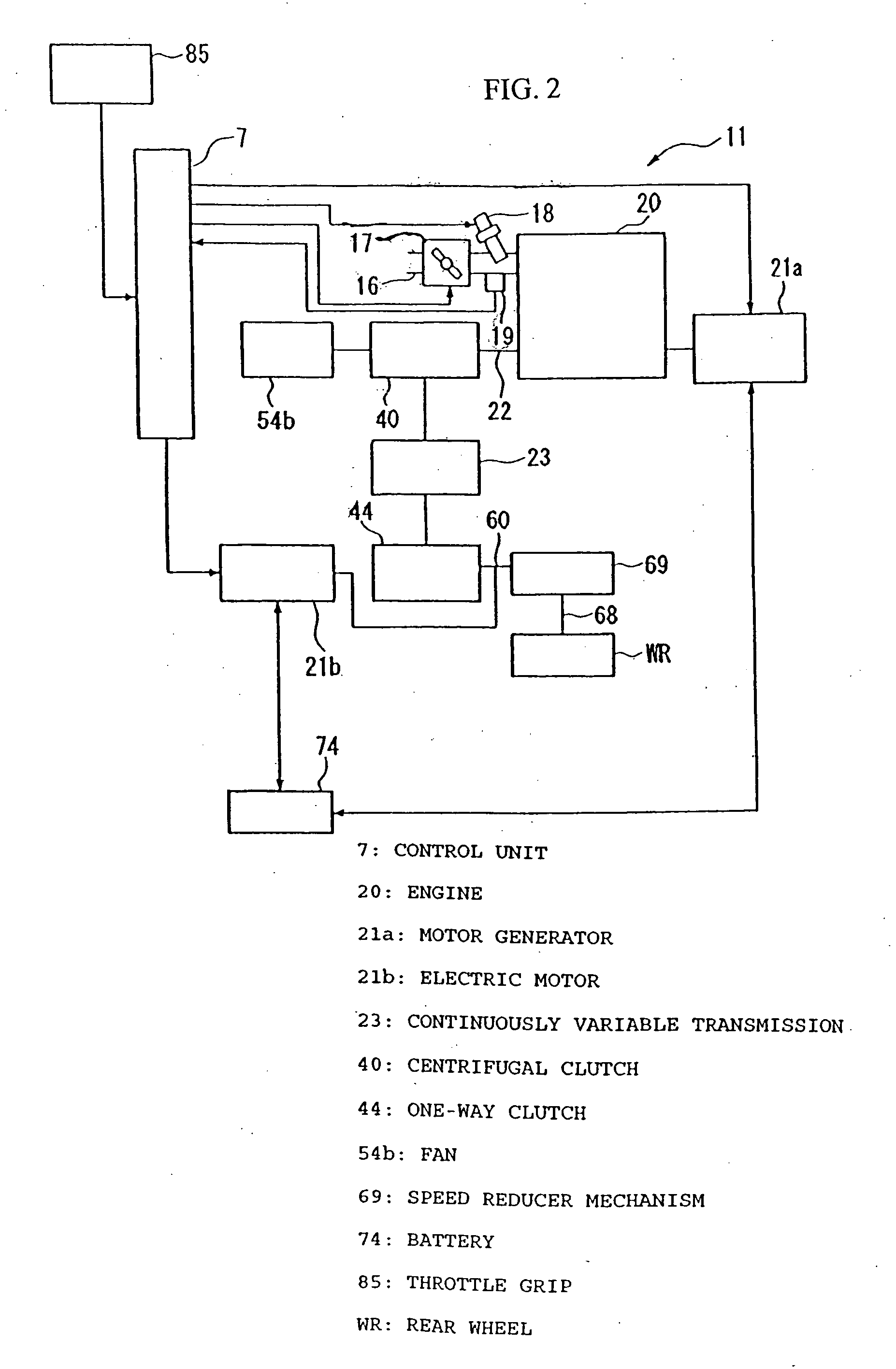
[0033] An example of a vehicle according to the selected illustrative embodiment is a hybrid scooter, which is an example of a saddle-type vehicle. As shown in FIG. 1, the vehicle has a power unit 11 including an electric motor 21b and is supported, together with a rear wheel WR, as a swingable unit which is pivotally mounted on a vehicle frame 10.

[0034] The vehicle has a front fork 1 on which a front wheel WF is supported by a shaft forwardly of a vehicle body. The front fork 1 is pivotally supported on a head pipe 2 of the vehicle frame 10. The front fork 1 has an upper end coupled to a handlebar 3 which can be operated to steer the vehicle. A down pipe 4 is mounted ...


PUM


Abstract

A vehicle having an electric generator control apparatus is provided for gradually reducing an engine load imposed due to electricity generation while a throttle valve is in the process of becoming fully open, thereby increasing a vehicle acceleration capability. The electric generator control apparatus is incorporated in a vehicle which has an ACG starter motor for generating electric power from power of an engine and supplying the generated electric power to a battery and other electric loads. When an engine throttle opening exceeds a preset value, the electric generator control apparatus continuously gradually reduces the amount of electric power generated by the ACG starter motor depending on the throttle opening in a fully opening direction which exceeds the preset value. The load imposed on the engine by electricity generation is gradually reduced, resulting in a corresponding increase in the acceleration capability of the vehicle.

Description

CROSS-REFERENCE TO RELATED APPLICATIONS [0001] The present invention claims priority under 35 USC 119 based on Japanese patent application No. 2004-233113, filed on Aug. 10, 2004. The subject matter of this priority document is incorporated by reference herein. BACKGROUND OF THE INVENTION [0002] 1. Field of the Invention [0003] The present invention relates to a control method and apparatus for an electric generator provided for generating electric power from engine power in a vehicle. The present invention also relates to a vehicle equipped with an apparatus of the type described. [0004] 2. Description of the Background Art [0005] Vehicles, such as saddle-type vehicles, including two-wheeled vehicles, are commonly provided with an electric generator, for generating electric power from engine power. The electric generator serves to supply electric power to operate accessories of the vehicle, including a battery, lights, etc. The generator normally generates electric power depending ...

Claims


Application Information

Patent Timeline
Patent Type & Authority Applications(United States)
IPC IPC(8): H02P9/04B60L50/16B62M23/02
CPCB60K6/442B60K6/543B60L11/14B60L2200/12B60W10/08B60W20/00Y02T10/70B60W2510/0604B60Y2200/12B62K2202/00Y02T10/6234Y02T10/7077B60W2300/365B60L50/16Y02T10/62Y02T10/7072B60W20/10
Inventor KOJIMA, HIROYUKIOZEKI, TAKASHITSUKADA, YOSHIAKIUCHISASAI, HIROAKI
Owner HONDA MOTOR CO LTD
Learn More