Hydraulic liquid pumping system
a pumping system and hydraulic technology, applied in the direction of liquid degasification, fluid coupling, separation process, etc., can solve the problem of limited area in which many hydraulic air compressor systems could be located
- Summary
- Abstract
- Description
- Claims
- Application Information
AI Technical Summary
Benefits of technology
Problems solved by technology
Method used
Image
Examples
example 1
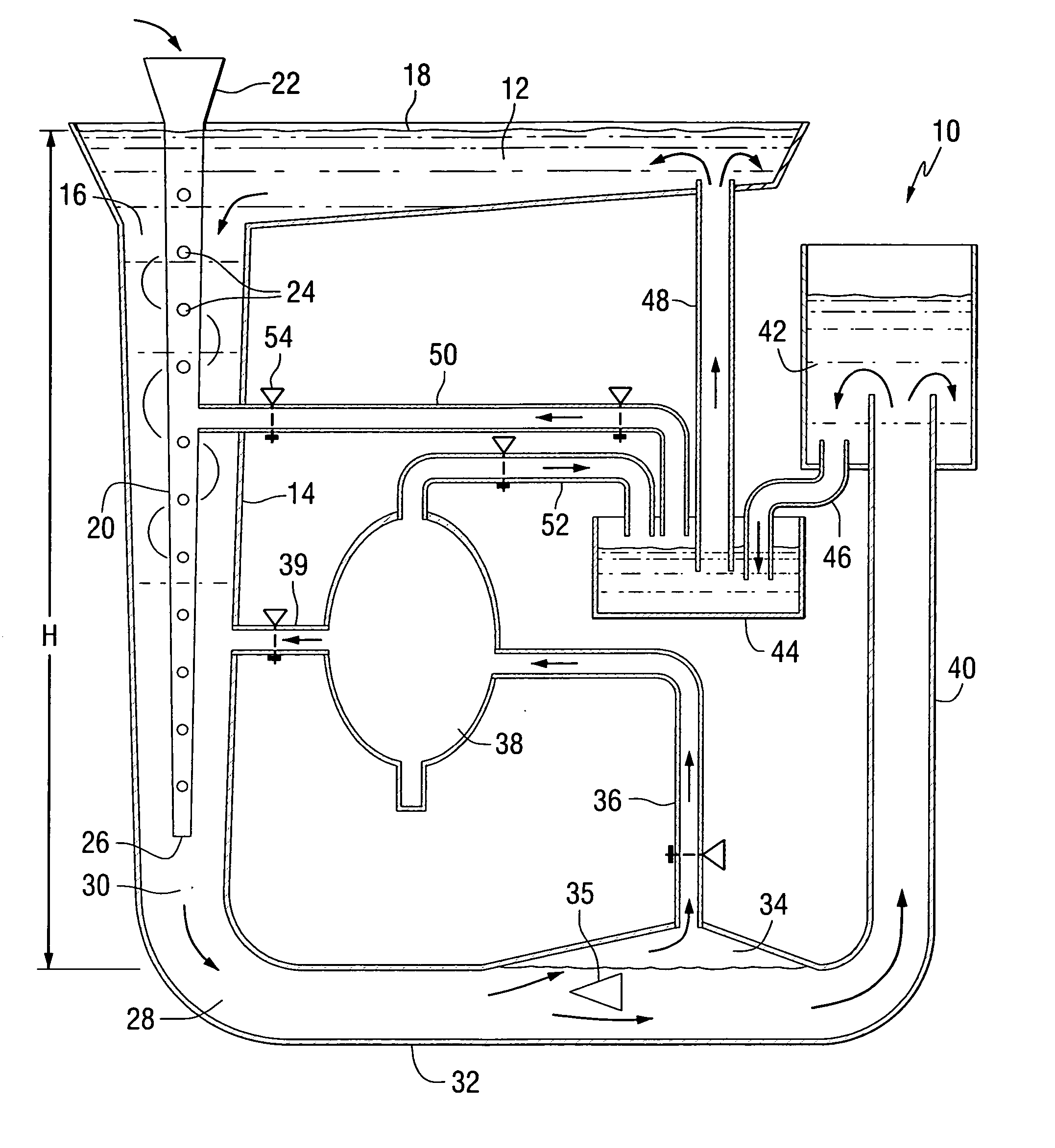
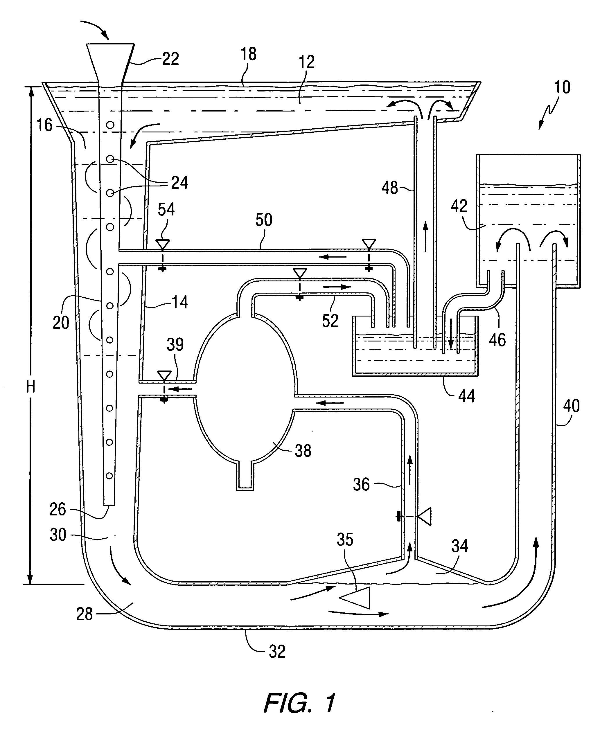
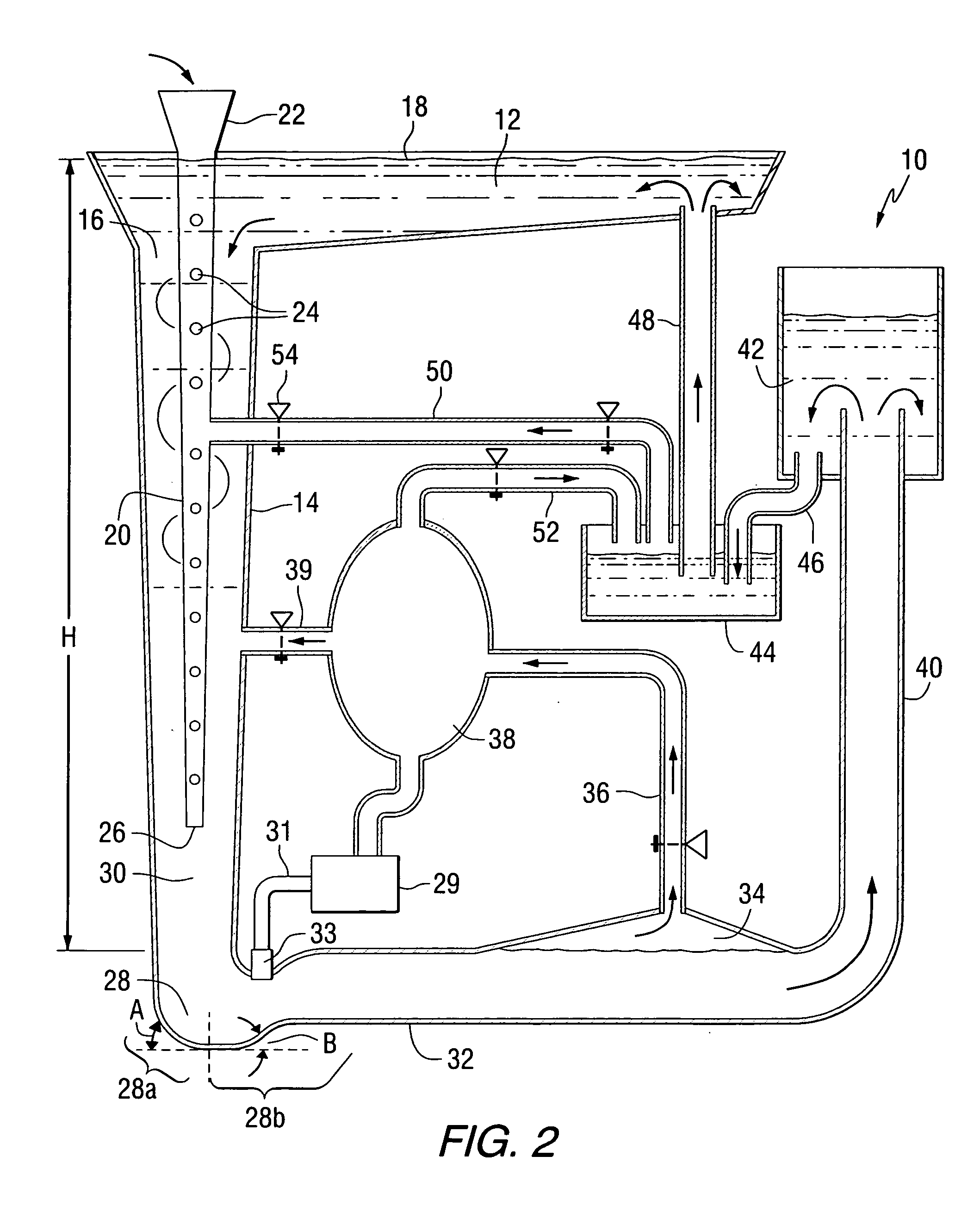
[0052] A partial system set-up was constructed to demonstrate that a relatively low air pressure can be used to pump water in a system as described above at a rate sufficient to sustain the water-air hydraulic cycle. With the proper height ratio of down pipe height to discharge pipe height the system can return liquid to the starting point within the system.
[0053] A first rack was positioned 234″ above the ground and a source liquid area tank having a 175-gallon volume was positioned on the first rack. The sides of the source liquid area tank were 14″ high. Water was fed from the source liquid area tank into a funnel at the top of a down pipe comprising a 3″ length of 4″ diameter pipe connected to a 4″ length of 3″ diameter pipe connected to an 8″ length of 2″ diameter pipe connected to a 1.5″ diameter plastic pipe having a length of 209″. The total length of the down pipe was 224″. Water was introduced to the funnel by a 2″ right angle pipe connected to a 1.375″ butterfly valve ex...
example 2
[0059] The second trial was made using the system of Example 1 with several modifications. A clear plastic 2″ diameter pipe was attached below the funnel. Inside the 2″ pipe a 1″ gas entrainment pipe with 0.125″ holes drilled into the sides was inserted. The gas entrainment pipe was used to supply air to the stream of water traveling down the down pipe. The 1″ plastic pipe had a 1.25″ outer diameter and the area difference between the 2″ inner diameter down pipe and the 1.25 outer diameter gas entrainment pipe was 1.914 in2. This was slightly bigger than the area of a 1.5″ inner diameter pipe (1.76 in2). For this evaluation, the areas of the two pipes when joined were considered equivalent. The 1″ pipe extended into the 2″ clear plastic pipe a length of 10 feet. The 1″ pipe extended upwards such that the 1″ pipe stuck out three feet above the funnel entrance and above the water level of the liquid source area tank. This was constructed to prevent water, seeking its own level, from c...
example 3
[0061] The third trial was made using the system of Example 2 with several modifications. The water height of the down pipe was increased by removing the funnel and the 1″ air pipe and connecting the down pipe to the liquid source area tank by a 90° 2″ fitting. This raised the water fall level to 242″ or 20.33 ft. This arrangement eliminated any air entrapment in the down pipe until the air was injected at the 212″ level down from the liquid source area tank. With this arrangement, the water flow is maximized since there is no air in the water prior to the introduction of the air entrainment pipe. At the 17.67 ft depth, the water pressure was measured at 7.65 psi.
[0062] Two air injectors were constructed to inject air into the falling water stream. The two injectors were made of ⅜″ copper tubing. One tube section was drilled with thirteen 1 / 16″ holes along a 6″ distance. The second tube section was made from a similar copper pipe but was cut at a 60° angle to the vertical, to expos...
PUM
 Abstract
Description
Claims
Application Information
 - R&D
- Intellectual Property
- Life Sciences
- Materials
- Tech Scout
- Unparalleled Data Quality
- Higher Quality Content
- 60% Fewer Hallucinations
Browse by: Latest US Patents, China's latest patents, Technical Efficacy Thesaurus, Application Domain, Technology Topic, Popular Technical Reports.
© 2025 PatSnap. All rights reserved.Legal|Privacy policy|Modern Slavery Act Transparency Statement|Sitemap|About US| Contact US: help@patsnap.com


