Storage device
- Summary
- Abstract
- Description
- Claims
- Application Information
AI Technical Summary
Benefits of technology
Problems solved by technology
Method used
Image

Examples
first embodiment
[0055]
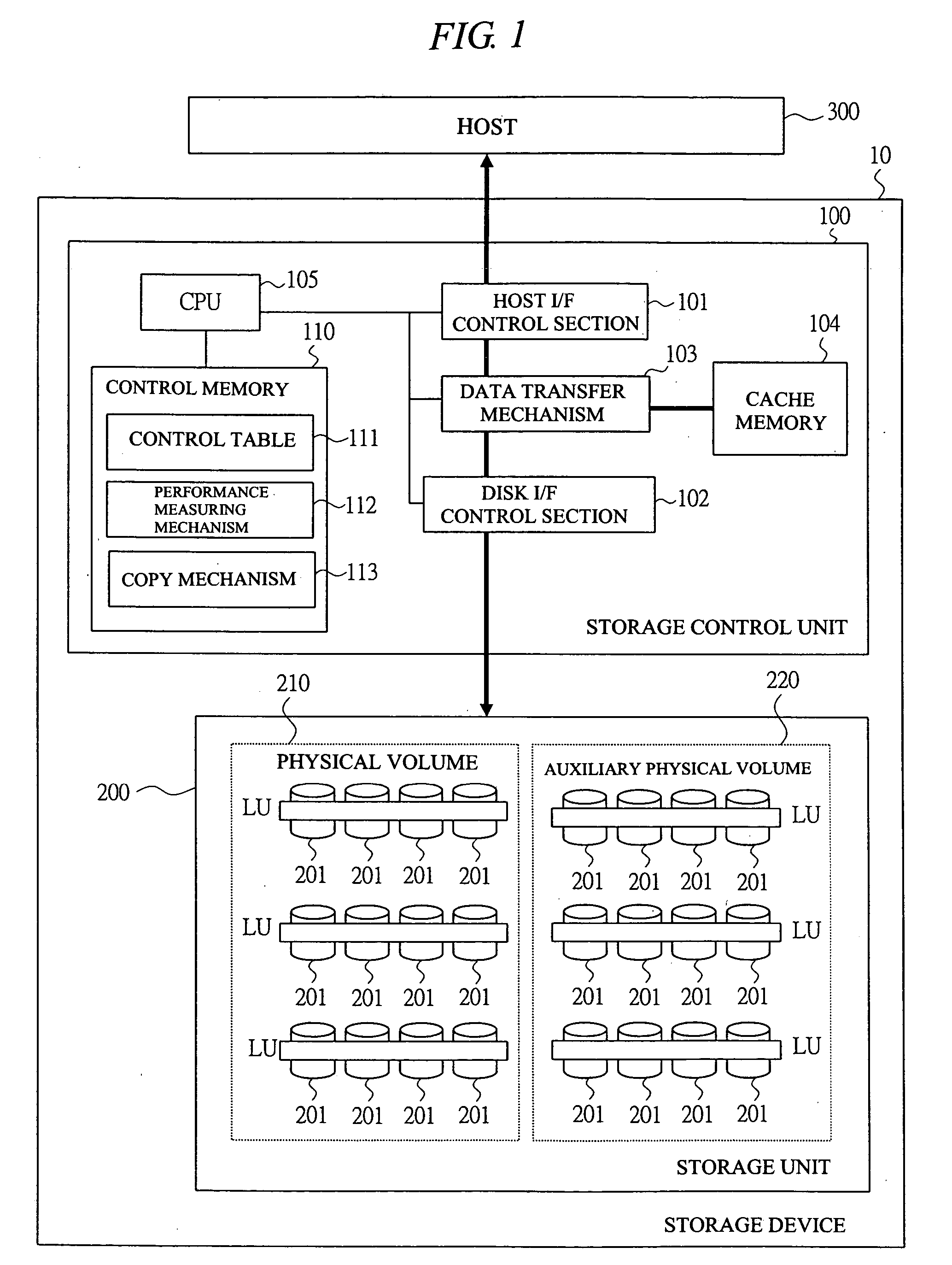
[0056] A description will be made of structure of a storage device according to a first embodiment of the present invention with reference to FIG. 1. FIG. 1 is a block diagram showing a structure of storage device according to a first embodiment of the present invention.
[0057] In FIG. 1, a storage device 10 comprises a storage control unit 100 and a storage unit 200.
[0058] The storage control unit 100 comprises a host I / F control section 101, a disk I / F control section 102, a data transfer mechanism 103, a cash memory 104, a central processing unit (CPU) 105, and a control memory 110.
[0059] The host I / F control section 101 is provided with a communications interface for establishing communication with a host (upper apparatus) 300, and has a function of exchanging a data input / output command etc. with the host 300.
[0060] The disk I / F control separation 102 is communicatably connected to a plurality of physical disk drives 201 storing the data and controls the storage unit 2...
second embodiment
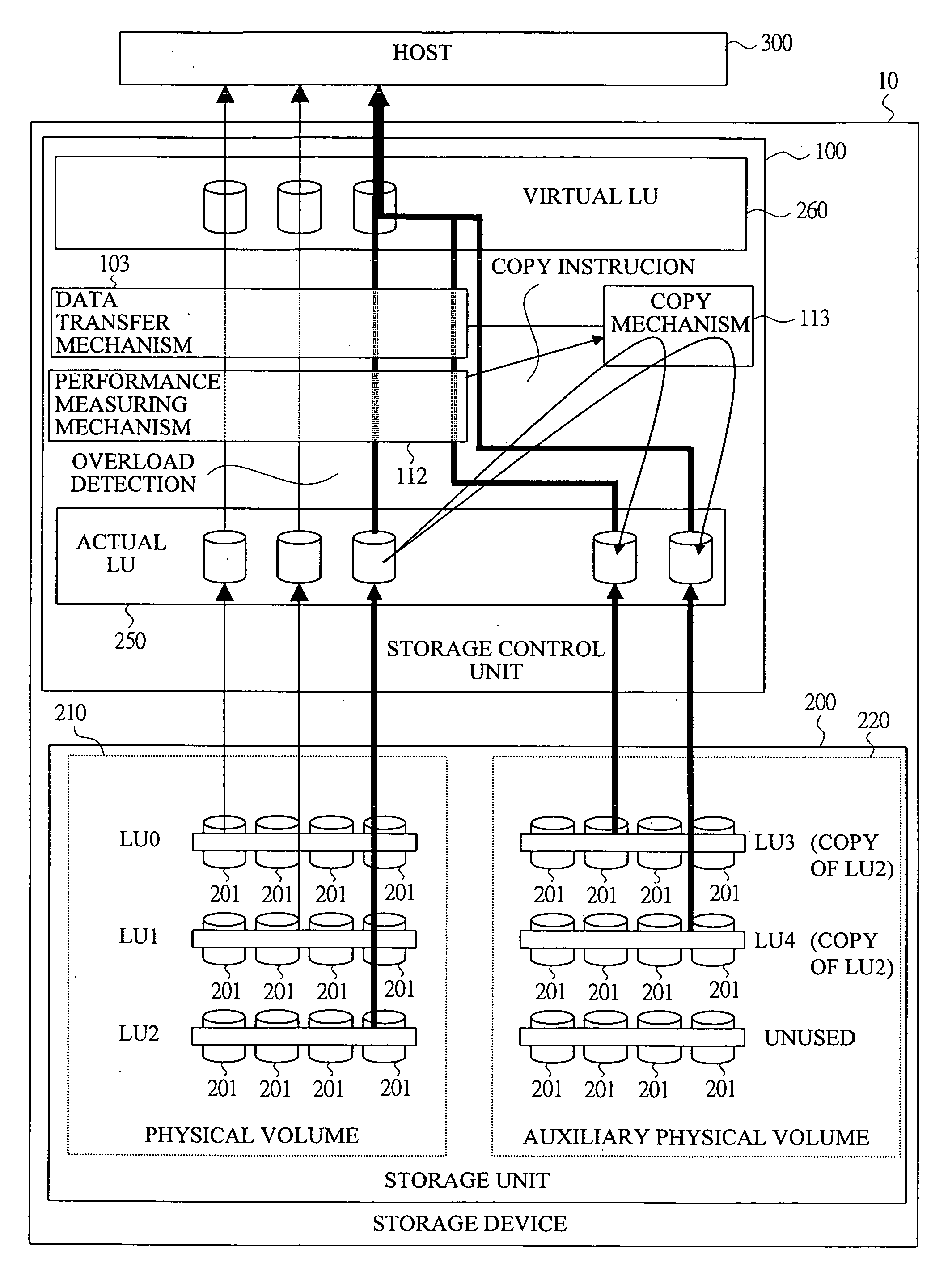
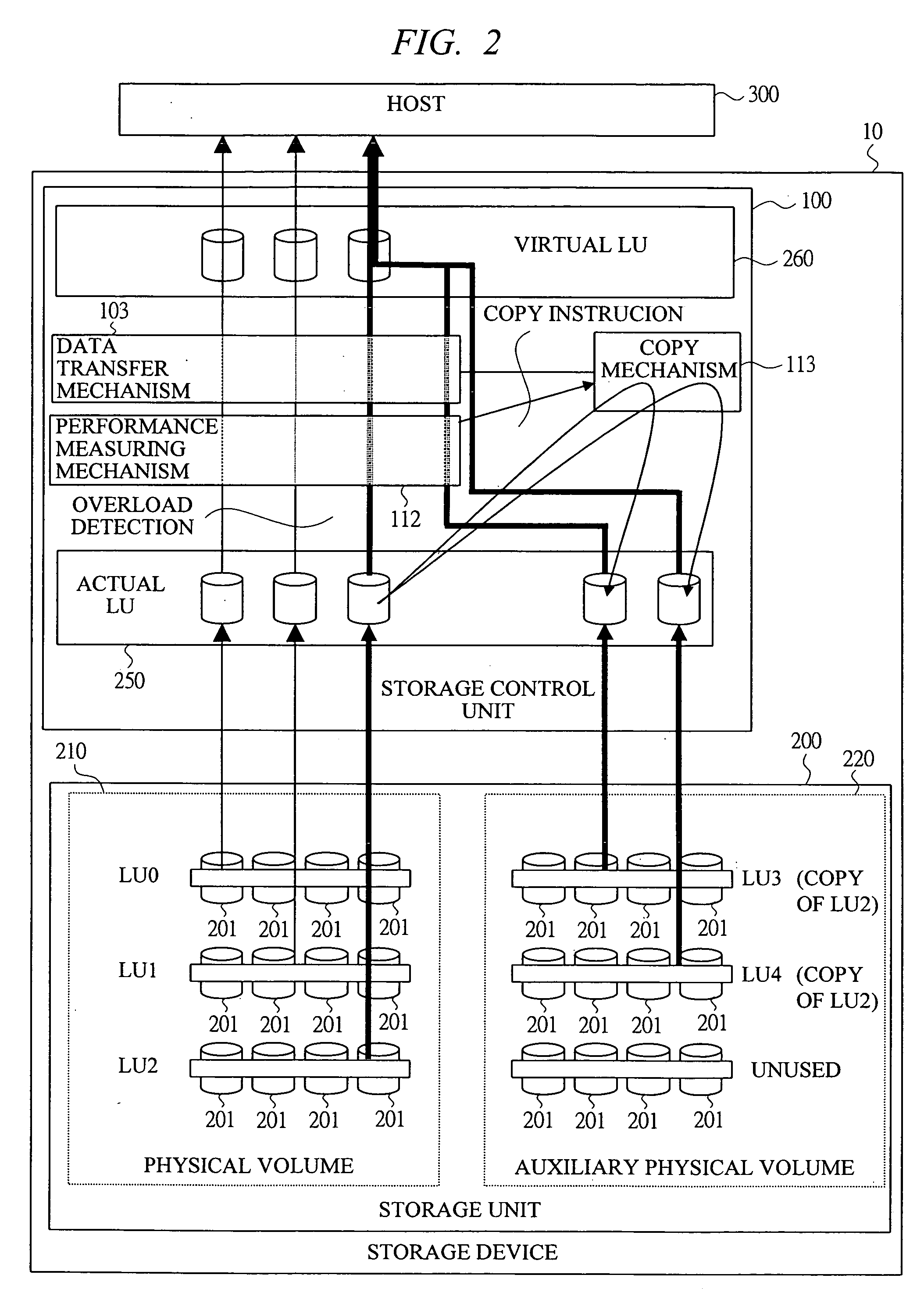
[0152] A second embodiment is such that, in the first embodiment, only a difference of the accessed data is copied instead of copying all the LUs within the physical volume 210 to the LU within the auxiliary physical volume 220 when the LU is in an overload state.
[0153] The structure of the storage device 10 according to the second embodiment is the same as that of the first embodiment.
[0154]
[0155] Next, a description will be made of an operation of generating a copy LU of a storage device according to the second embodiment of the present invention with reference to FIGS. 12 and 13. FIG. 12 is a flow chart showing an example of the storage device according to the second embodiment of the present invention, and FIG. 13 is a flow chart showing another example of the operation of generating the copy LU of the storage device according to the second embodiment of the present invention.
[0156] First, as shown in FIG. 12, if no vacancy is provided in the auxiliary physical volume 220 at ...
third embodiment
[0187] An third embodiment is such that a user terminal connected to the storage control unit 100 is provided in the first or second embodiment and the overload of the LU is detected by using a user interface of the user terminal and an instruction for starting the copy is outputted.
[0188] The storage device 10 according to the third embodiment has the same structure as that of the first embodiment and has a structure in which the user terminal is connected to the storage control unit 100.
[0189]
[0190] A description will be made of an operation of a load distribution processing of the storage device according to the third embodiment of the present invention with reference to FIG. 16. FIG. 16 is an explanatory view for describing a load distribution processing of the storage device according to the third embodiment of the present invention.
[0191] In FIG. 16, a user terminal 400 is connected to the storage control unit 100, and has a structure in which a overload of the LU can be de...
PUM
 Abstract
Description
Claims
Application Information
 - R&D
- Intellectual Property
- Life Sciences
- Materials
- Tech Scout
- Unparalleled Data Quality
- Higher Quality Content
- 60% Fewer Hallucinations
Browse by: Latest US Patents, China's latest patents, Technical Efficacy Thesaurus, Application Domain, Technology Topic, Popular Technical Reports.
© 2025 PatSnap. All rights reserved.Legal|Privacy policy|Modern Slavery Act Transparency Statement|Sitemap|About US| Contact US: help@patsnap.com