
Plasma or serum separation membrane and filter apparatus including the plasma or serum separation membrane

a separation membrane and plasma technology, applied in the field of plasma or serum separation membrane and filter apparatus, can solve the problems of unsatisfactory filtering speed, inability to securely stop filtration, and more likely to occur hemolysis, and achieve reliable and rapid separation of plasma.

Active Publication Date: 2006-02-09
TOYO TOYOBO CO LTD +2
View PDF6 Cites 107 Cited by
  • Summary
  • Abstract
  • Description
  • Claims
  • Application Information

AI Technical Summary

Benefits of technology

[0009] In consideration of the above circumstances of the conventional arts, it is an object of the present invention to provide a plasma or serum separating membrane enabling reliable and rapid separation of plasma or serum components from blood without causing breakage of erythrocytes, and to provide a filter apparatus using the plasma or serum separating membrane.
[0010] As a result of diligent research for separation of plasma or serum components from corpuscles in blood, the inventors of the present application found that plasma or serum components can be separated from corpuscles without causing hemolysis by using a separation membrane having pores of specific constitution and accomplished the present invention.
[0015] In a further specific aspect of the plasma or serum separating membrane of the present invention, the plasma or serum separating membrane is used as a corpuscle blocking membrane for preventing contamination by corpuscles.

Problems solved by technology

However, the method disclosed in Japanese Examined Patent Publication No. 2-23831 (1990) had an economic problem because high cost is required to produce a disposable product due to the hollow fiber.
The method of Japanese Examined Patent Publication No. 6-64054 enables separation of plasma or serum, however the filtering speed is still unsatisfactory.
Additionally, in the blood in which fibrin or the like precipitates, hemolysis was more likely to occur since clogging was more likely to occur during the separation process.
In the method of Japanese Unexamined Patent Publication JP-A 11-285607 (1999), since the filtering speed changes between bloods of different hematocrits and viscosities, it was impossible to securely stop the filtration at the point when filtration of plasma or serum completed.

Method used


Image

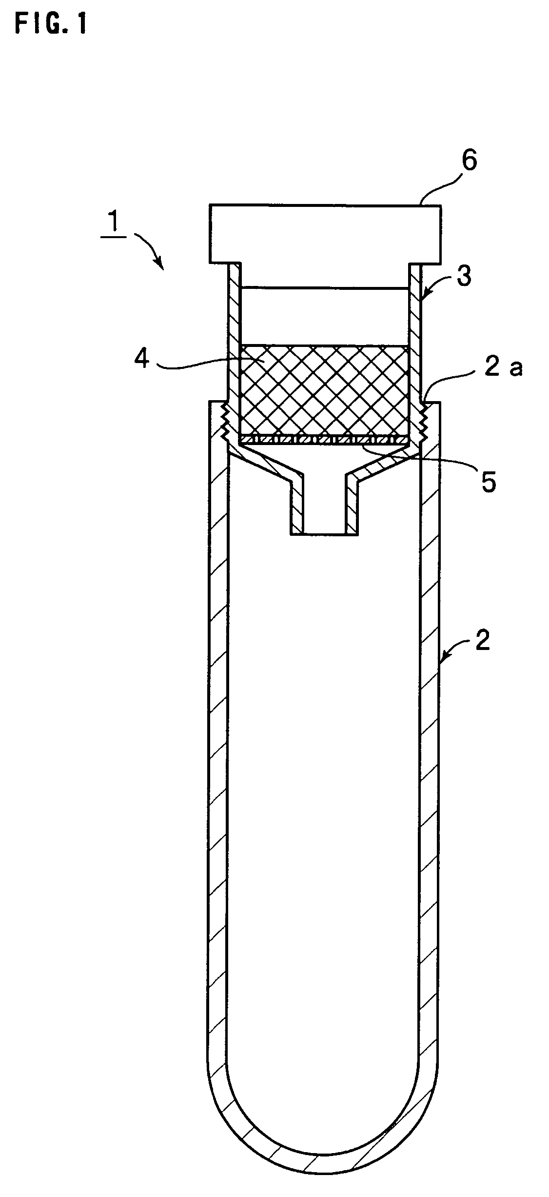
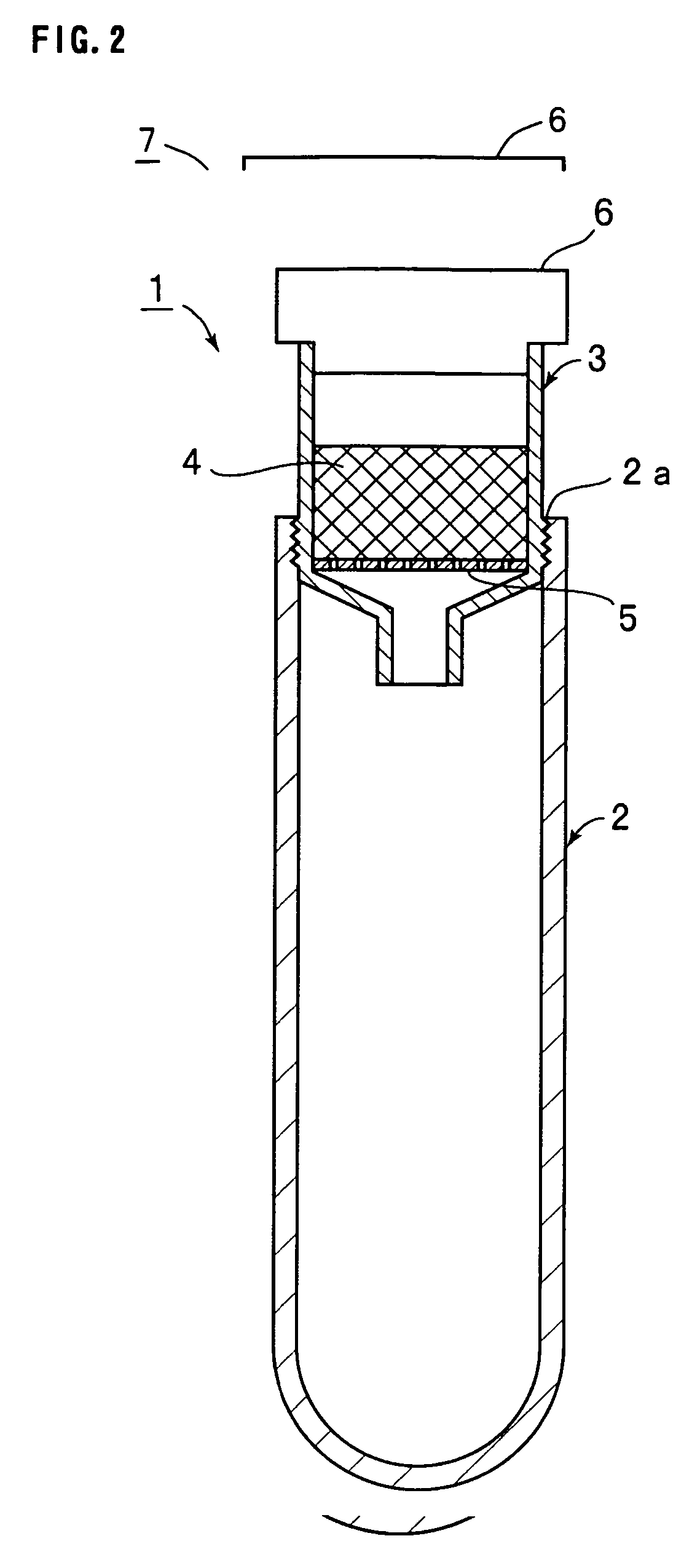
  • Plasma or serum separation membrane and filter apparatus including the plasma or serum separation membrane
  • Plasma or serum separation membrane and filter apparatus including the plasma or serum separation membrane
  • Plasma or serum separation membrane and filter apparatus including the plasma or serum separation membrane

Examples


example 1

[0121] A separation membrane made of polycarbonate having a thickness of 10 μm (manufactured by Millipore Corporation, product number: GTTP04700, separation membrane having a plurality of through holes with a circular cross section shape of 0.2 μm in pore size) was prepared. The separation membrane was cut into a piece of 13 mm in diameter and the piece was set into a commercially available filter cartridge (manufacture by Millipore Corporation, trade name: Sphinex filter holder Sx0130000).

example 2

[0122] An evaluation sample was prepared in the same manner as Example 1 except that the diameter of the through holes was changed to 0.6 μm.

example 3

[0123] An evaluation sample was prepared in the same manner as Example 1 except that the diameter of the through holes was changed to 2.0 μm.


PUM

PropertyMeasurementUnit
Fractionaaaaaaaaaa
Diameteraaaaaaaaaa
Diameteraaaaaaaaaa

Abstract

A Plasma or serum separation membrane that enables omitting centrifugal separation, is free from hemolysis attributed to destruction of red blood cells and realizes easy and rapid separation of plasma or serum from blood; and a filter apparatus including the plasma or serum separation membrane. In particular, a plasma or serum separation membrane being a membrane for separation of plasma or serum from blood and having a void ratio of 30% or below; and a filter apparatus comprising a filter member capable of attaining movement of plasma swifter than movement of blood cells and a plasma or serum separation membrane connected in series with a rear side of the filter member.

Description

FIELD OF THE INVENTION [0001] The present invention relates to plasma or serum separating membranes for use in separation of plasma or serum components in blood containing corpuscles, and more specifically, to a plasma or serum separating membrane and a filter apparatus enabling separation of plasma or serum components without causing breakage of erythrocytes. BACKGROUND ART [0002] Conventionally, a variety of separating membranes have been proposed for removing corpuscles from blood to obtain plasma or serum required for laboratory tests. [0003] For example, Japanese Examined Patent Publication No. 2-23831 (1990) discloses a method of colleting plasma from blood using a hollow fiber having fine pores of 0.05 to 1 μm in diameter, a porosity of outer surface of not more than 40%, and a porosity of inner surface of not less than 60%. [0004] Japanese Examined Patent publication No. 6-64054 (1994) proposes a method of separating plasma or serum through a fiber layer having a mean diamet...

Claims


Application Information

Patent Timeline
IPC IPC(8): A01N1/02C12M1/34B01D61/18B01D63/08B01D69/02B01D69/06G01N33/48
CPCB01D61/18B01D69/02B01L3/502B01L3/5082B01L2300/047B01L2300/0681Y10T436/25G01N33/491Y10T436/255Y10T436/11Y10T436/25125Y10T436/25375B01L2400/0487B01D63/08B01D69/06B01D2311/2649
Inventor TOGAWA, KATSUYAOKAMOTO, RYUSUKEISOGAWA, HIRONOBU
Owner TOYO TOYOBO CO LTD
Learn More