Linear motion guide unit

Active Publication Date: 2006-02-09
NIPPON THOMPSON
View PDF2 Cites 9 Cited by
  • Summary
  • Abstract
  • Description
  • Claims
  • Application Information

AI Technical Summary

Benefits of technology

[0018] With the linear motion guide unit constructed as stated earlier, the slider used in the prior linear motion guide unit may be made simple in construction, easier in assembly so as to reduce error cumulative in assembly operations. According to the present invention, the carriage alone is allowed to simply fit in between forward and aft end plates of the carriage casing to install the carriage with accuracy within the carriage casing, while the forward and aft end caps are just applied on the outward end surfaces of the carriage casing. The carriage, end caps and carriage casing are all joined together with no fasteners including bolts, screws, and so on used conventional assembly operations, but mutual fit-engagement of mating parts mutually complementary to one another. This helps lessen any error cumulative in assembly operations even with making certain of steady joining relation among the components with accuracy. In other words, the carriage is first fit into the carriage casing and, then, the end caps 4 are fit on the outward edges of the carriage casing in such a way that the mating parts of the end caps fit into their complementary mating parts of the carriage to keep steadily the carriage against up-and-down movement in the carriage casing.

Problems solved by technology

With the prior linear motion guide unit in which the carriage and a pair of the end caps are installed inside the carriage housing all at once as recited earlier, nevertheless, the assembly operations need several more chores that might give rise to error cumulative in assembly operations.
The prior linear guide arrangement could not still get out of error cumulative in assembly operations to fit the combination of the carriage member with the forward and aft reversing bodies into the guide carriage housing.

Method used


Image

  • Linear motion guide unit
  • Linear motion guide unit
  • Linear motion guide unit

Examples


Embodiment Construction

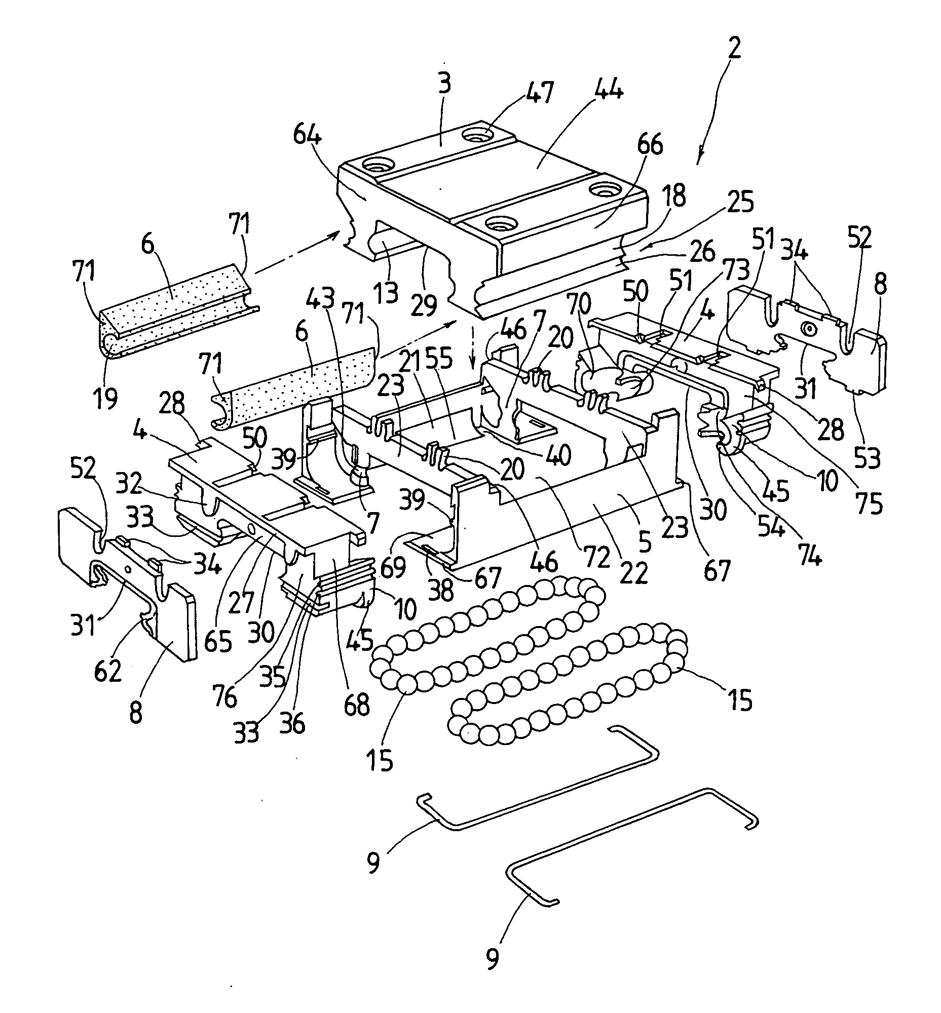
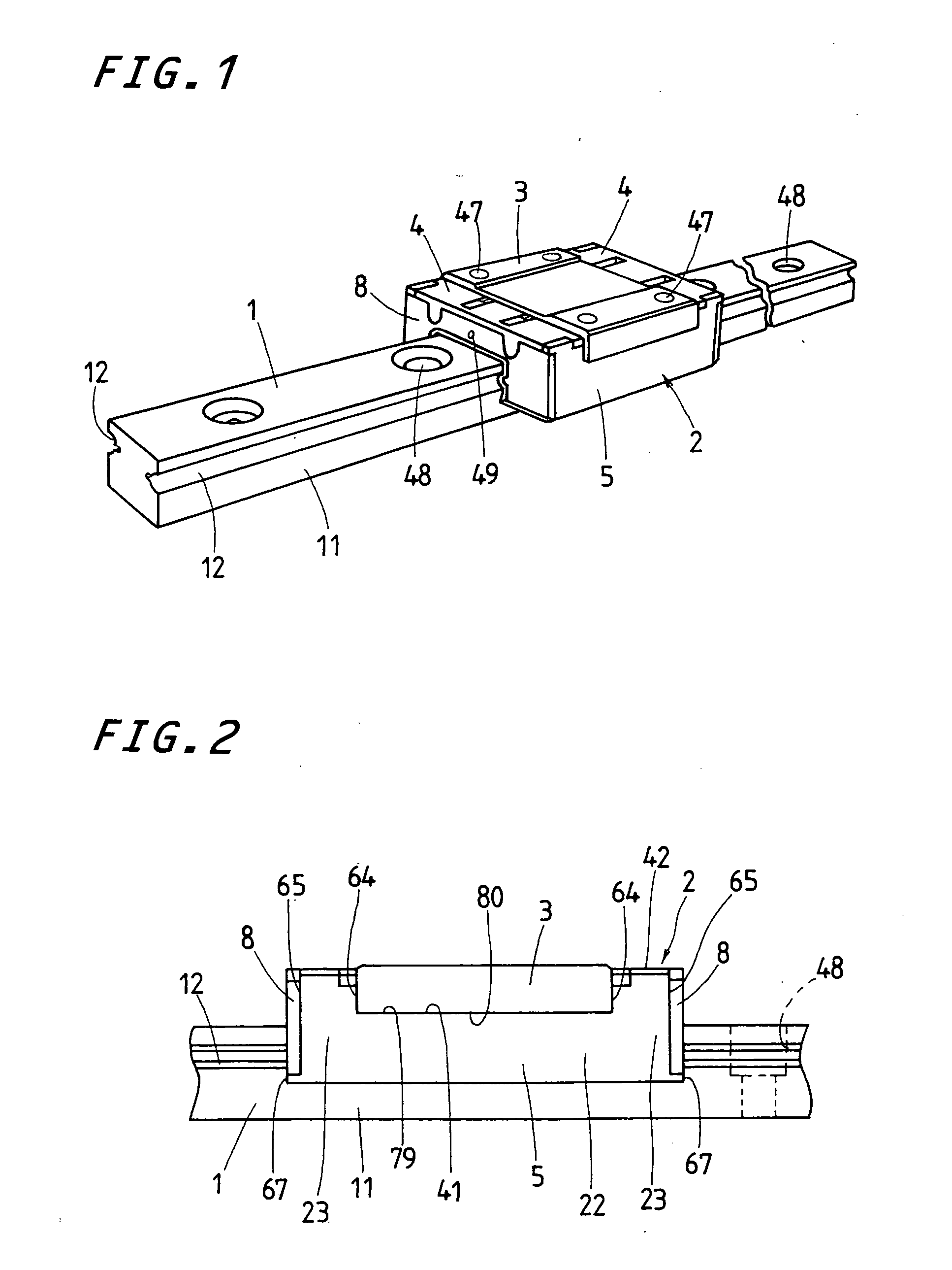
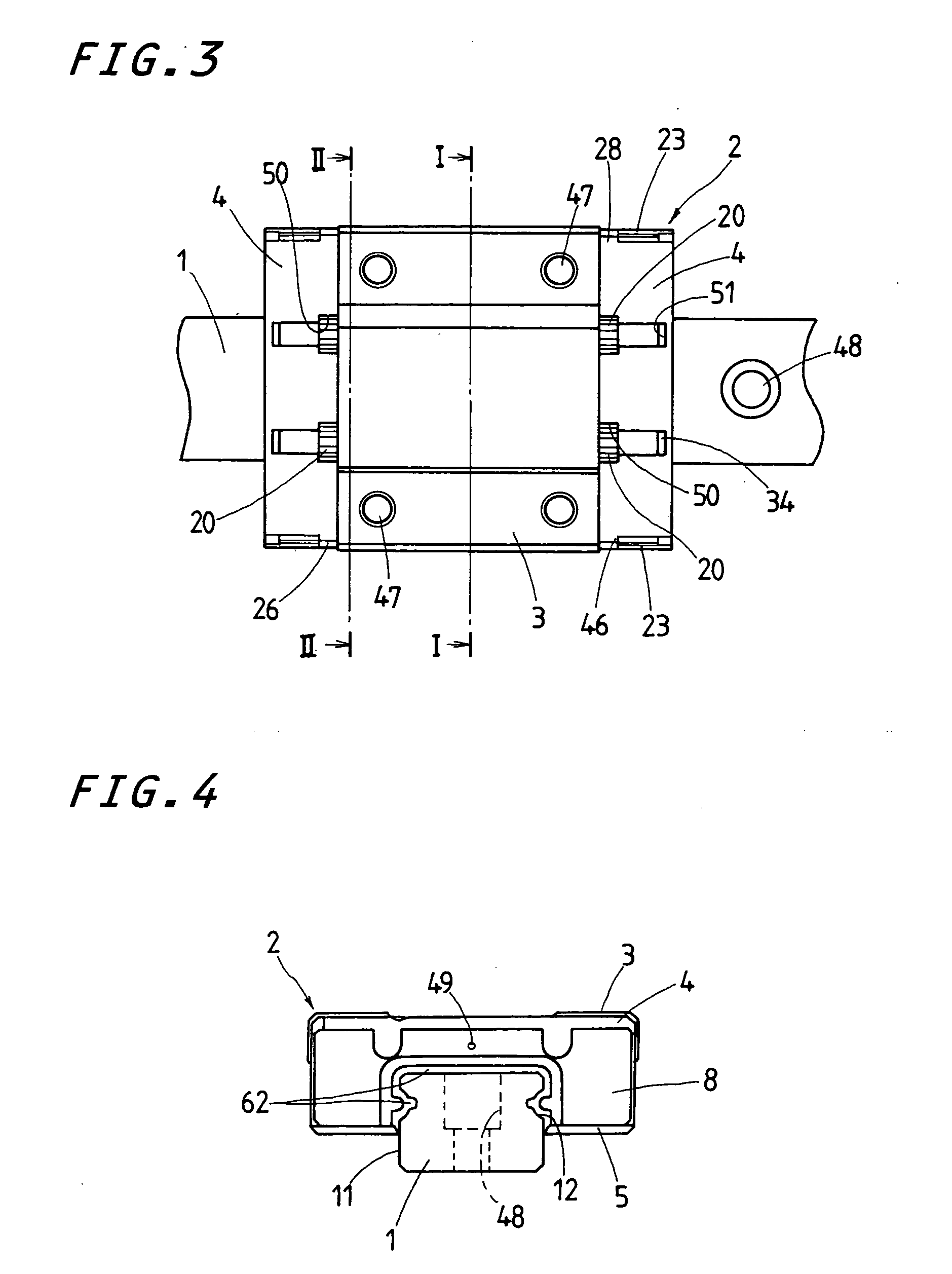
[0043] A linear motion guide unit according of the present invention will be explained in detail by way of a preferred version with reference to the accompanying drawings. The linear motion guide unit according to the present invention is adapted for use in any relatively sliding components in machinery as diverse as various robots, semiconductor manufacturing machines, precision machines, measurement / inspection instruments, medical instruments, micromachines, machine tools, and so on, and more particular constructed as small as possible in size, even with making sure of desired performance including high stiffness, smooth traveling, high precision, and so on.

[0044] The linear motion guide unit disclosed hereinafter is made of a type in which a slider 2 fits over and conforms to a guide rail 1 and the slider 2 is constituted with a carriage, carriage casing, end caps and end seals. More than one slider may fit over the guide rail 1 for relative movement one another.

[0045] The line...


PUM


Abstract

A linear motion guide unit is disclosed, in which components required for a slider are all joined together with no fasteners including bolts, screws, and so on used conventional assembly operations, but mutual fit-engagement of any components with their mating counterparts. This allows reducing the number of components to cope with a modern tendency of miniaturization of the linear motion guide system. The slider includes a carriage casing composed of end panels facing forward and aft ends of a carriage, one to each end, and side panels facing widthwise opposing sides of the carriage, one to each, the end and side panels being connected integrally to surround the carriage. To complete the slider, the carriage first fits between the end panels of the carriage casing. Then, end caps are applied to outward surfaces of the end panels of the carriage casing and joined together by making fit-engagement of mating parts on the end caps with counterparts on the carriage and carriage casing complementary to the mating parts.

Description

FIELD OF THE INVNTION [0001] The present invention relates to a linear motion guide unit ready for miniaturization in size and comprised of a guide rail having a raceway groove thereon and a slider that fits over and conforms to the guide rail for movement relative to the guide rail by virtue more than one rolling element. BACKGROUND OF THE INVENTION [0002] Linear motion guide units are conventionally used in any relatively sliding arrangement in diverse fields of machinery such as various industrial robots, semiconductor manufacturing apparatus, precision machines, and so on. Most prior linear motion guide units are in general comprised of a guide rail and a slider that fits over the guide rail for relative movement, the slider being composed of a carriage and end caps, which are joined together with fastening means such as screws and so on. [0003] Meanwhile, linear motion guide units are now known in which there is no need of fastening means such as tightening screws to join a car...

Claims


Application Information

Patent Timeline
IPC IPC(8): F16C29/06
CPCF16C29/06F16C29/0657F16C29/0609F16C29/0611
Inventor ISHIHARA, TOYOHISA
Owner NIPPON THOMPSON
Why Eureka
Try Eureka