
Modular rack assemblies for sealed lead acid batteries

a technology of lead acid batteries and modular rack assemblies, which is applied in the direction of cell components, cell component details, electrochemical generators, etc., can solve the problems of system and/or battery damage and failure, disruption of power sources, and catastrophic system failure, and achieve the effect of cost saving and easy assembly

Inactive Publication Date: 2006-02-09
KIM MFG
View PDF7 Cites 50 Cited by
  • Summary
  • Abstract
  • Description
  • Claims
  • Application Information

AI Technical Summary

Benefits of technology

The present invention is a modular system that meets the seismic requirements of the Telcordia GR-63 Core Nebs Zone 4 standard. The rack is easy and economical to manufacture and meets the seismic requirements. The modules are designed to prevent torquing or twisting and are secure in their arrangement. The base configuration is designed to withstand high loads from turn over moments. The modules can be assembled at the site and easily stacked one on top of the other. The invention provides a novel design that allows for easy assembly and tight space installation. The technical effects of the invention include ease of assembly, cost savings, and seismic protection for battery systems.

Problems solved by technology

Even though the shelves and the channel support members provide stability to the columns, they are subject to some twisting and turning when seismic loads are applied during testing and the distortion of the structure can in some instances be severe enough to cause system and / or battery damage and failure which could disrupt the power source.
High seismic loads can create large turnover moments causing anchors to pull or break out of the concrete floor resulting in a catastrophic system failure.
Even though these systems are generally effective for the purposes intended, none of them meet the most stringent seismic requirements of the Telcordia GR-63 Core Nebs Zone 4 applications.

Method used


Image

  • Modular rack assemblies for sealed lead acid batteries
  • Modular rack assemblies for sealed lead acid batteries
  • Modular rack assemblies for sealed lead acid batteries

Examples


Embodiment Construction

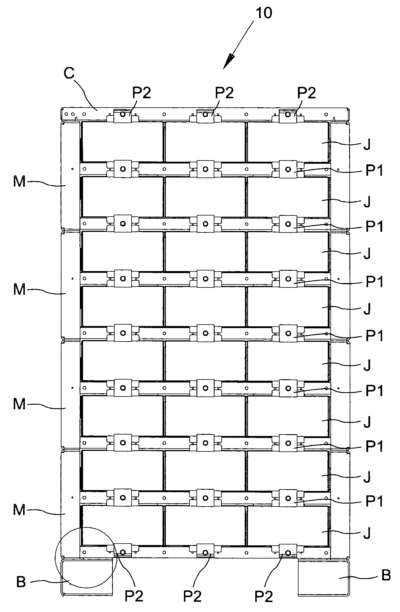
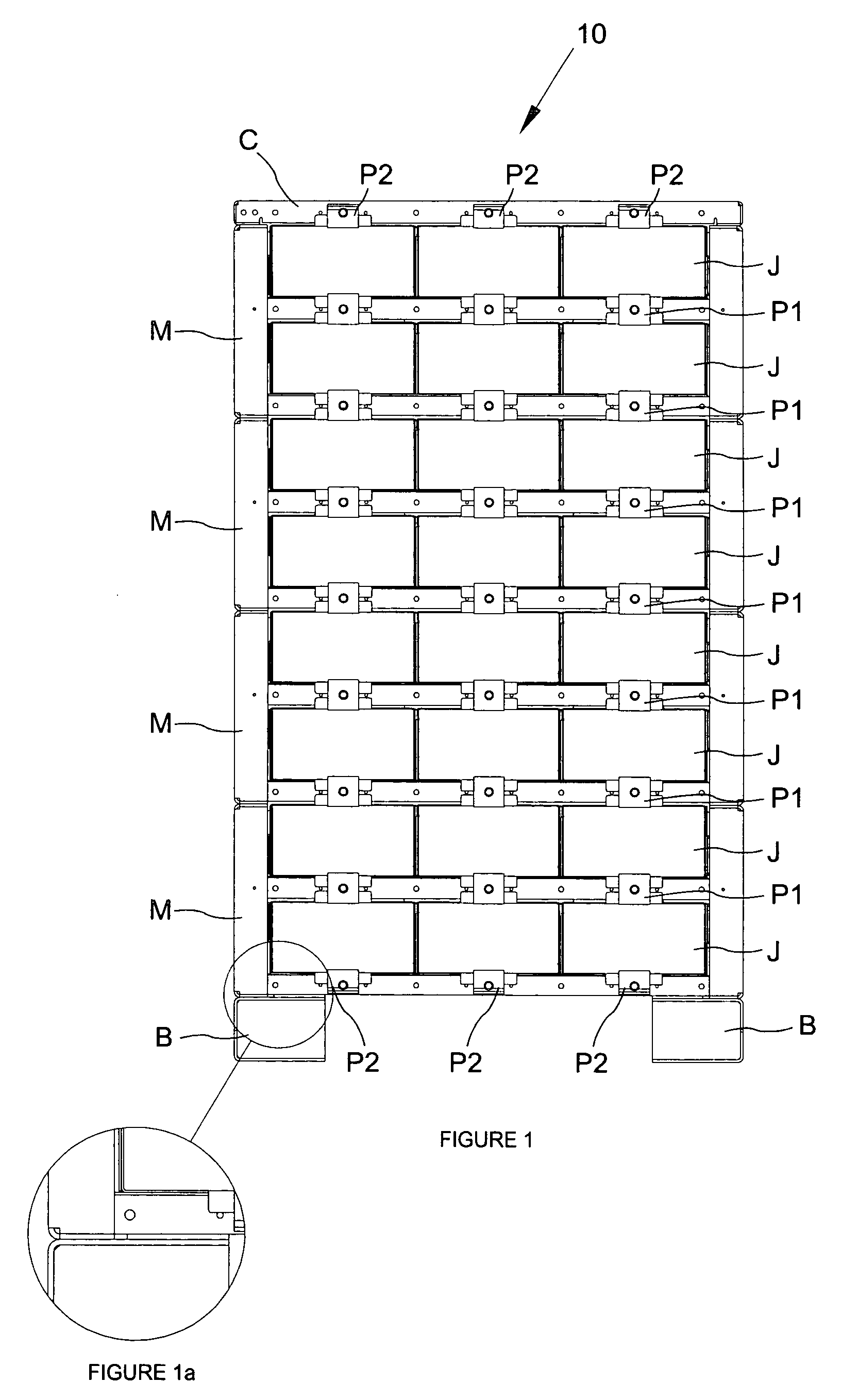
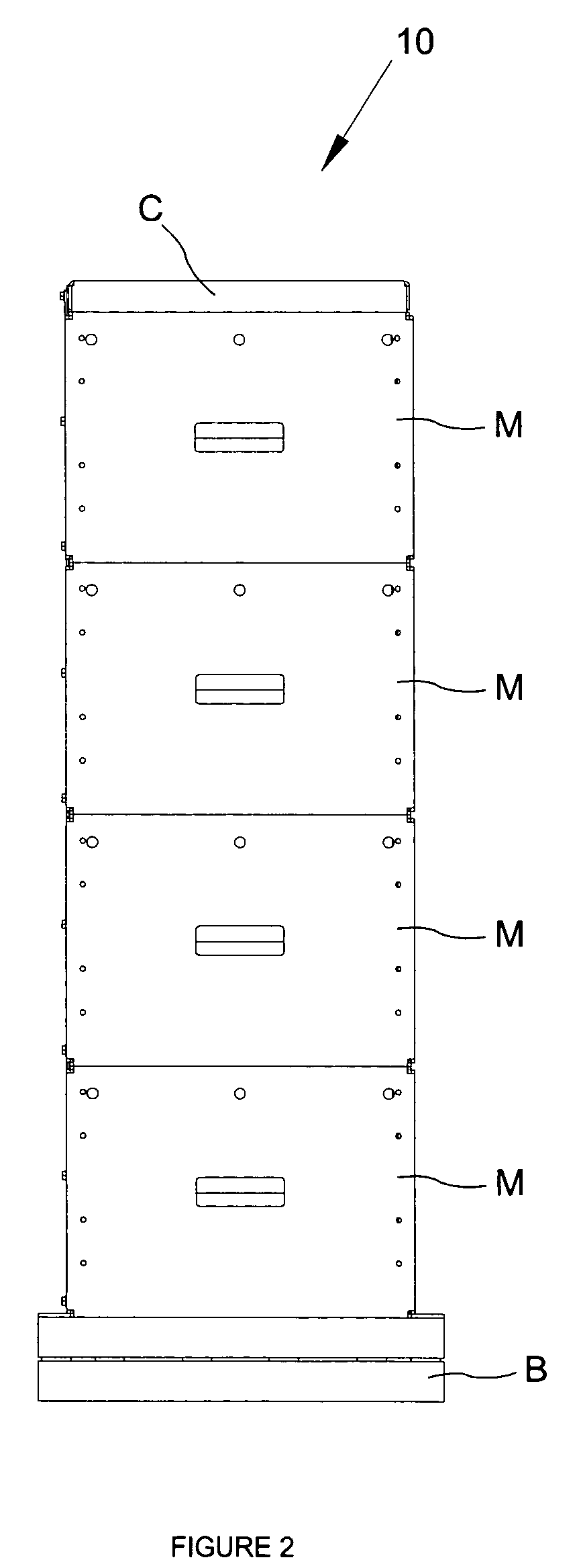
[0038] Referring now to the drawings and particularly to FIG. 7, thereof, there is shown a modular battery rack assembly in accordance with the present invention generally designated by the numeral 10. As illustrated, the rack assembly 10 comprises a series of box-like modules M accommodating multiple rows of batteries housed in jackets J and a top cover C. The basic construction of each module is essentially the same and as illustrated can be made with plural tiers so that varying voltage systems can be designed.

[0039] The module M as best illustrated in FIG. 18 comprises a pair of side panels 12a, 12b of identical construction having a generally rectangular face 14a, 14b, top and bottom flanges 16a, 16b, 17a, 17b projecting perpendicularly to the top and bottom edge of the face 14a, 14b. Side flanges 18a, 18b, 19a, 19b connect the top and bottom flanges 16a, 16b, 17a and 17b. The flanges as shown are formed integrally with the faces 14a, 14b to form a one piece side panel. The to...


PUM

PropertyMeasurementUnit
seismic stressaaaaaaaaaa
areaaaaaaaaaaa
heightaaaaaaaaaa

Abstract

A module for a battery system supporting batteries during seismic stress comprising a pair of side panels, each panel formed of material such as steel shaped to define a generally rectangular face and top and bottom flanges extending generally perpendicularly to the face along top and bottom edges thereof and side flanges formed integrally with the face and top and bottom flanges, a base plate having means for mounting the module to a support surface having a generally U-shaped channel formed integrally along the front and rear edges of the base plate, a rear panel extending between and nested in the side panels and secured thereto and the base plate, at least one pair of front and rear support channels extending between the side panels, a shelf for batteries supported on the base plate and support channels, a support channel extending vertically between the top and bottom flanges, and means for securing modules stacked one on top of another along the top and bottom flanges.

Description

FIELD OF THE INVENTION [0001] The present invention relates to improvements in modular rack assemblies for supporting and storing batteries. More specifically, the present invention provides a modular system characterized by novel features of construction and arrangement providing an uninterruptible back-up power source which meets the seismic requirements of Telcordia GR-63 Core Nebs Zone 4. DESCRIPTION OF THE PRIOR ART [0002] A typical prior art battery rack system is shown in U.S. Pat. No. 6,719,150B2 issued Apr. 13, 2004 and entitled BATTERY RACK AND SYSTEM. This battery rack and system comprises a frame device for supporting a plurality of batteries and thereby providing a power source to maintain operations when the primary power source shuts down. The rack comprises a pair of end frame members mounted in upstanding spaced apart relation by a plurality of vertically spaced elongated channel support members secured at opposite terminal ends to the vertical columns of the end fr...

Claims


Application Information

Patent Timeline
Patent Type & Authority Applications(United States)
IPC IPC(8): H02J7/00H01M50/209H01M50/224
CPCH01M2/1077H01M10/06H01M10/5065H01M10/5018H01M10/5004H01M10/627H01M10/613H01M10/6562Y02E60/10H01M50/209H01M50/224
Inventor MARRAFFA, ANDEW
Owner KIM MFG
Learn More