Welding process for large structures

Active Publication Date: 2006-02-09
AIRBUS OPERATIONS LTD
View PDF9 Cites 4 Cited by
  • Summary
  • Abstract
  • Description
  • Claims
  • Application Information

AI Technical Summary

Benefits of technology

[0009] providing two metal components to be welded together, each component having a length, a width, a height and a surface to be welded, the surface to be welded of at least one of the metal components including a feature extending substantially the length of the component, the feature reducing the contact width of the surfaces to be welded of the two components to less than the width of each component; and
[0011] By reducing the contact width of the surfaces it becomes feasible to weld together components which would otherwise be difficult or impossible to weld together. Also, since the structure is formed by more than one component, each component can be of smaller cross-section than the whole structure and can therefore be made longer from a given volume of material. This is, for example, advantageous when a large spar of an aircraft wing is being manufactured, since the limits on the volume of a billet of material that can be rolled, forged or extruded mean that it is not feasible to produce a full length spar in one piece. Conventionally the spar is produced in lengths that are joined end to end. By using the present invention, however, each component can be produced in a longer length from a given volume of material reducing or eliminating the need for lengthwise joining of the spar. In certain structures, the invention can give rise to even greater advantages if more than two components are joined together side-by-side to form a very long, single structure.
[0013] By providing a feature on the surface to be welded of at least one of the metal components, which reduces the contact width between the two components, it is possible to use friction stir welding to join the two components, even when the two components are large. Preferably, the at least one weld has a constant width and extends along the length of the components to be joined. Preferably, the at least one weld has no discontinuities along its length.
[0026] providing two elongate metal billets, a surface to be welded of at least one of the metal billets including a rebate extending substantially the length of the billet, the rebate reducing contact width between surfaces to be welded of the two billets to substantially less than the width of each billet; then

Problems solved by technology

However, fabricated spars are labour-intensive to assemble, requiring the drilling of many holes and the setting of rivets and bolts.
They are also expensive because the assembly process requires sophisticated tooling, and they are heavier because of the material overlap and the rivets and bolts.
They are also at greater risk of fatigue damage due to the large number of fastener holes.
Friction stir welding is a well-known and useful welding process but is, unfortunately, limited by the depth of welding that can be achieved.
Currently the maximum depth of material which can be reliably welded by friction stir welding is about 6 to 10 mm, which makes it apparently unsuitable for welding components of large structures such as spars.

Method used


Image

  • Welding process for large structures
  • Welding process for large structures
  • Welding process for large structures

Examples


Embodiment Construction

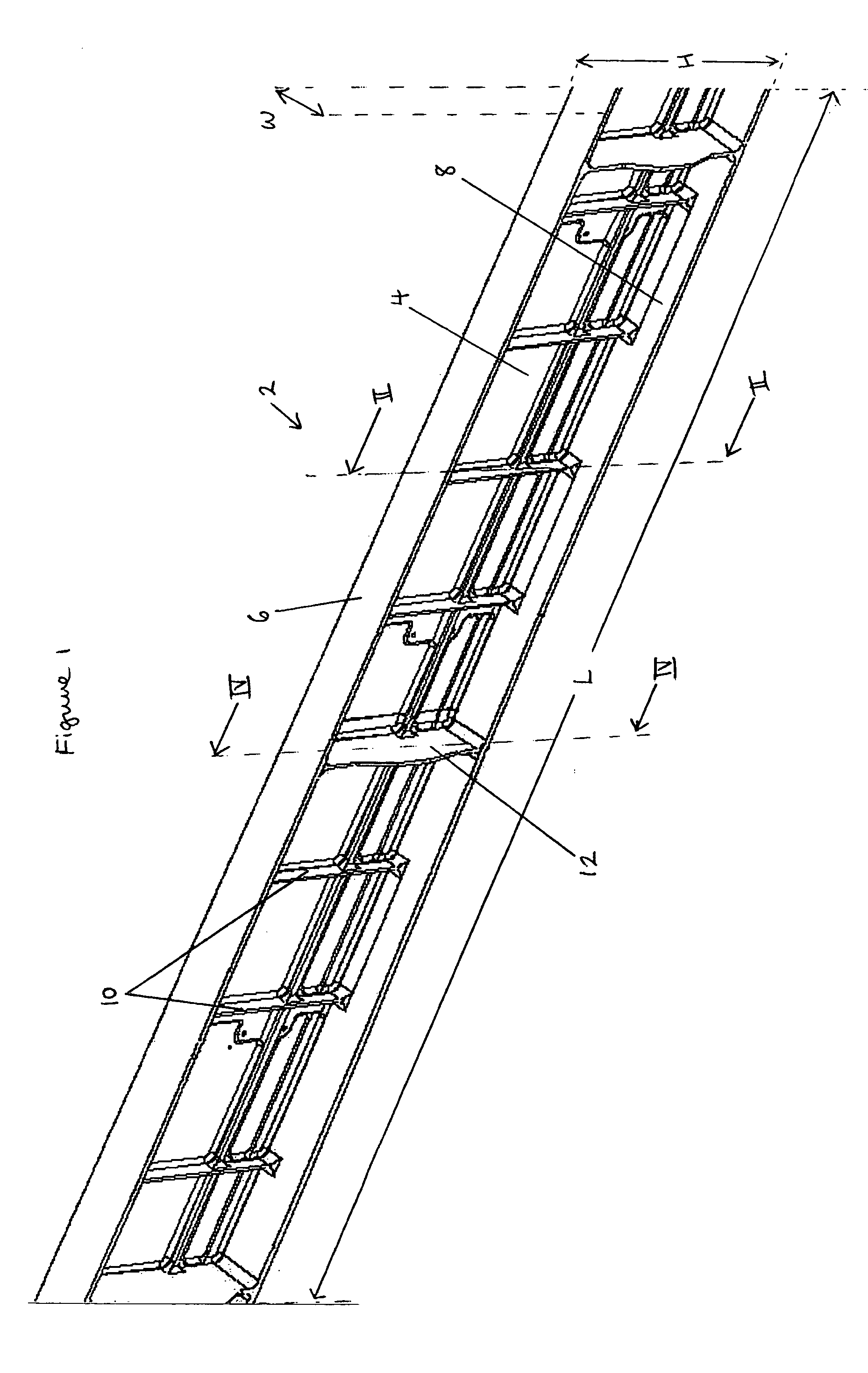
[0054]FIG. 1 is a perspective view of a section of spar 2. The spar section has a web 4 which is relatively narrow, an upper flange 6 and a lower flange 8. At regular intervals along the length L of the spar are stiffeners 10 for strengthening the spar. The stiffeners 10 are the same height H as the spar but extend further in the width direction W. Thus, the stiffeners appear as plates whose planes are perpendicular to the spar length. It will be seen that the height of the spar section decreases from one end of the spar section to the other. At intervals along the length of the spar, ribs (not shown) are attached to certain of the stiffeners 10 at locations 12.

[0055]FIG. 1 shows an integrally-machined spar section. The entire spar is formed from several separately-machined sections (like that in FIG. 1) which are then joined together (e.g. by rivets and bolts), since the size of each section is limited by the volume of material that can be rolled or extruded. The stiffeners 10 are...


PUM

PropertyMeasurementUnit
Structureaaaaaaaaaa
Lengthaaaaaaaaaa
Widthaaaaaaaaaa

Abstract

There is provided a method for welding together two metal components to form a large structure suitable for use as an aerospace component. The method comprises the steps of providing two metal components to be welded together, each component having a length, a width, a height and a surface to be welded, the surface to be welded of at least one of the metal components including a feature extending substantially the length of the component, the feature reducing the contact width of the surfaces to be welded of the two components to less than the width of each component; and welding together the components. There is also provided a large structure so created. There is also provided a method for welding together two metal components to form a part or a whole of a spar for a wing for an aircraft and a spar so created.

Description

BACKGROUND OF THE INVENTION [0001] This invention relates to a method of welding together two metal components to form a large structure which may be suitable for use as an aerospace component and to a large structure so created. In this context, an aerospace component means one that forms part of a fixed-wing aircraft, a helicopter, a missile, a satellite, a space structure or the like. The invention relates particularly, but not exclusively, to a method of welding together two large metal components to form a part or a whole of a spar for a wing of an aircraft and to a spar so created. [0002] In many applications it is necessary to weld together two large metal components. In many applications, it is also useful if the two components have different properties, thereby creating a structure having certain properties in one section and different properties in another section. For example, a spar in the wing of an aircraft is subject to forces in its upper section different from those...

Claims


Application Information

Patent Timeline
IPC IPC(8): B23K31/02B23K20/12B23K26/20B23K33/00
CPCB23K20/1225B23K2203/10B23K33/004B23K26/20B23K26/21B23K2103/10
Inventor DAY, ROGER ANTHONYTIGHE, DAVID JOHN
Owner AIRBUS OPERATIONS LTD
Why Eureka
Try Eureka