Insertion contact for arrangement at a contact support

a technology of arrangement and contact support, which is applied in the direction of electrically conductive connection, coupling device connection, electrical apparatus, etc., can solve the problems of contact damage, degrading electrical transmission value, and affecting the performance of contact,

Active Publication Date: 2014-09-09
LUMBERG CONNECT
View PDF7 Cites 0 Cited by
  • Summary
  • Abstract
  • Description
  • Claims
  • Application Information

AI Technical Summary

Benefits of technology

[0010]The essential advantage of the invention lies in the configuration of the support arm contacting the contact support with the stamped side of the support arm, wherein the printed circuit board is the contact support in the illustrated embodiment. Compared to conventional insertion contacts which contact a contact surface of the opposite contact with a rolled side while the support arm also contacts with a rolled side, the contact width of the support arm according to the invention is significantly lower and thus only corresponds to the material thickness of the contact. When there is a respective requirement, the support arm that is relatively inflexible compared to known devices can be used for increasing the contact forces between the contact arm and the contact surface. An alternating opposite arrangement of plural insertion contacts adjacent to one another causes the contact arm of the insertion contact to contact a contact surface on the top side of the contact support with a rolled side of the insertion contact, whereas the adjacent second insertion contact contacts the contact surface on the bottom side of the contact support with the contact arm of the insertion contact. Since the support arm of the insertion contact according to the invention is much narrower than the associated contact arm, the insertion contacts can be nested into one another at the contact support through an alternating arrangement of insertion contacts according to the invention, so that opposite contact arms are separated by the contact support and arranged overlapping.
[0011]In one embodiment, it is provided that the connection arm is arranged at an edge of the contact arm and oriented essentially orthogonal to the contact arm with the rolled side of the connection arm. In this embodiment, due to the arrangement of the connection arm, also the support arm is arranged laterally of the contact arm and below the contact arm, so that a maximum amount of overlap of adjacent contact arms is provided for an opposed arrangement of plural contacts at a contact support. Arrangements are also feasible that have an angle that differs from 90°.
[0012]However, an insertion contact is preferred in particular, wherein the insertion contact is characterized in that the connection arm is configured elbowed and the support arm arranged at the connection arm is oriented parallel to the longitudinal center axis of the contact arm and centrally below the contact arm.
[0013]For this insertion contact, the arrangement of the support arm parallel to the longitudinal center axis and centrally below the contact arm provides an essentially even distribution of the contact forces between the contact surfaces of opposite contact and contact arm.
[0014]It is furthermore provided that the contact arm supports the connection member, in particular a cutting fork. It is also feasible that the connection member is configured as a crimped connection spring clamp, screw clamp, solder joint or as a different connection type in order to connect the conductor.
[0015]It is furthermore feasible that the opposite contact forms a second contact surface below the contact support, wherein the second contact surface is electrically connected with the support arm. This embodiment contacts the opposite contact on both sides in an electrical manner which provides advantages with respect to electricity transmission.

Problems solved by technology

These insertion contacts also bear the risk of damaging the finishing layers due to the typically burred and rough stamping edge in combination with high contact forces during insertion on the conductive paths.
This counteracts the effect of the high contact forces by degrading the electrical transmission values by destroying or damaging the finishing layers.
Thus, in particular, the grid dimensions of plug connectors according to the Rast 2.5 standard are not easily reducible while maintaining the respective technical features.

Method used


Image

  • Insertion contact for arrangement at a contact support
  • Insertion contact for arrangement at a contact support
  • Insertion contact for arrangement at a contact support

Examples


Embodiment Construction

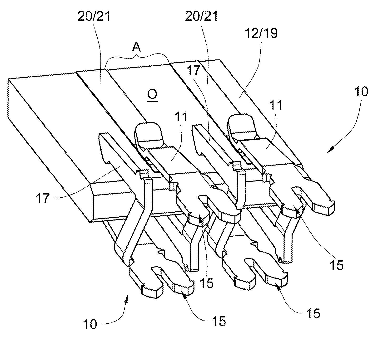
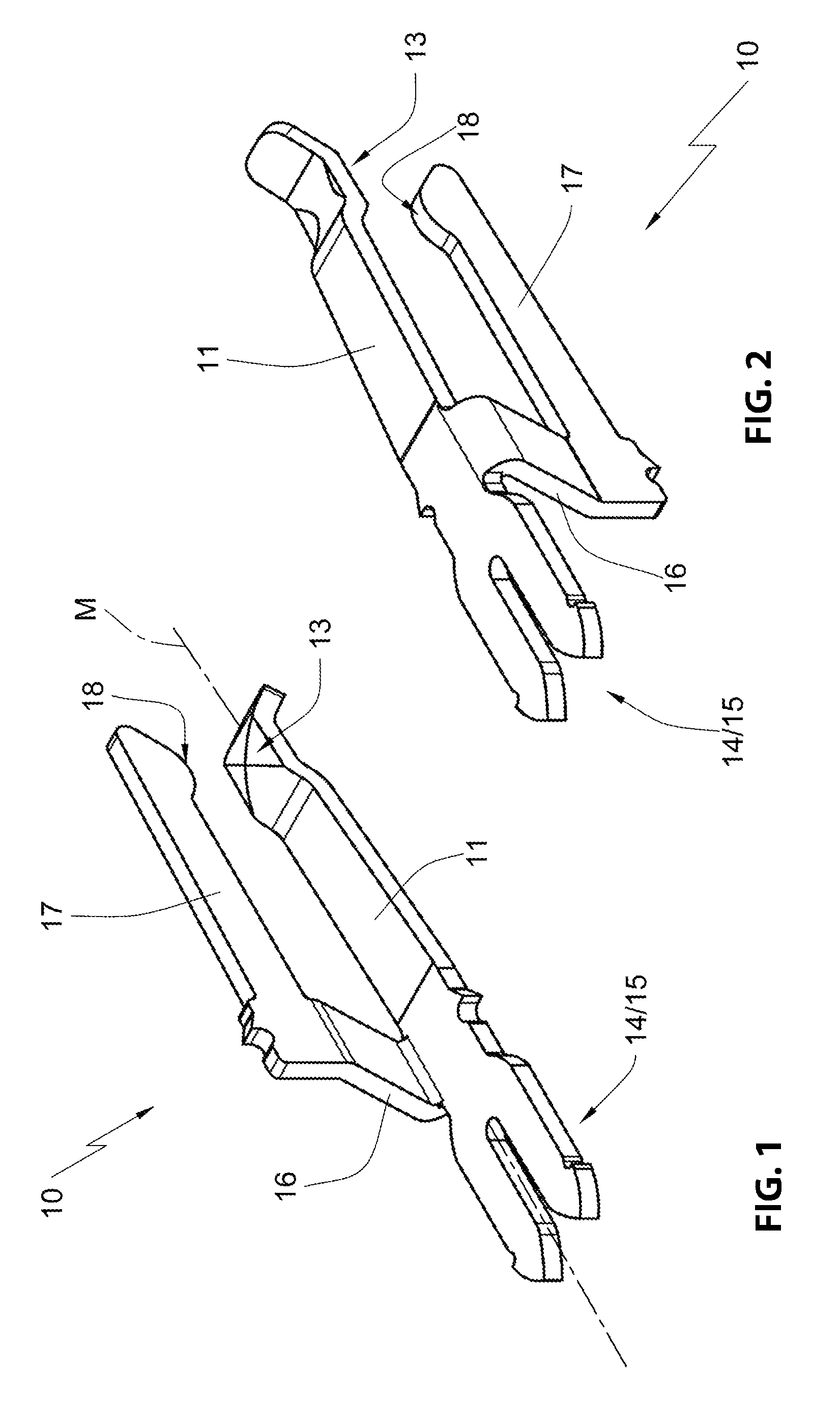
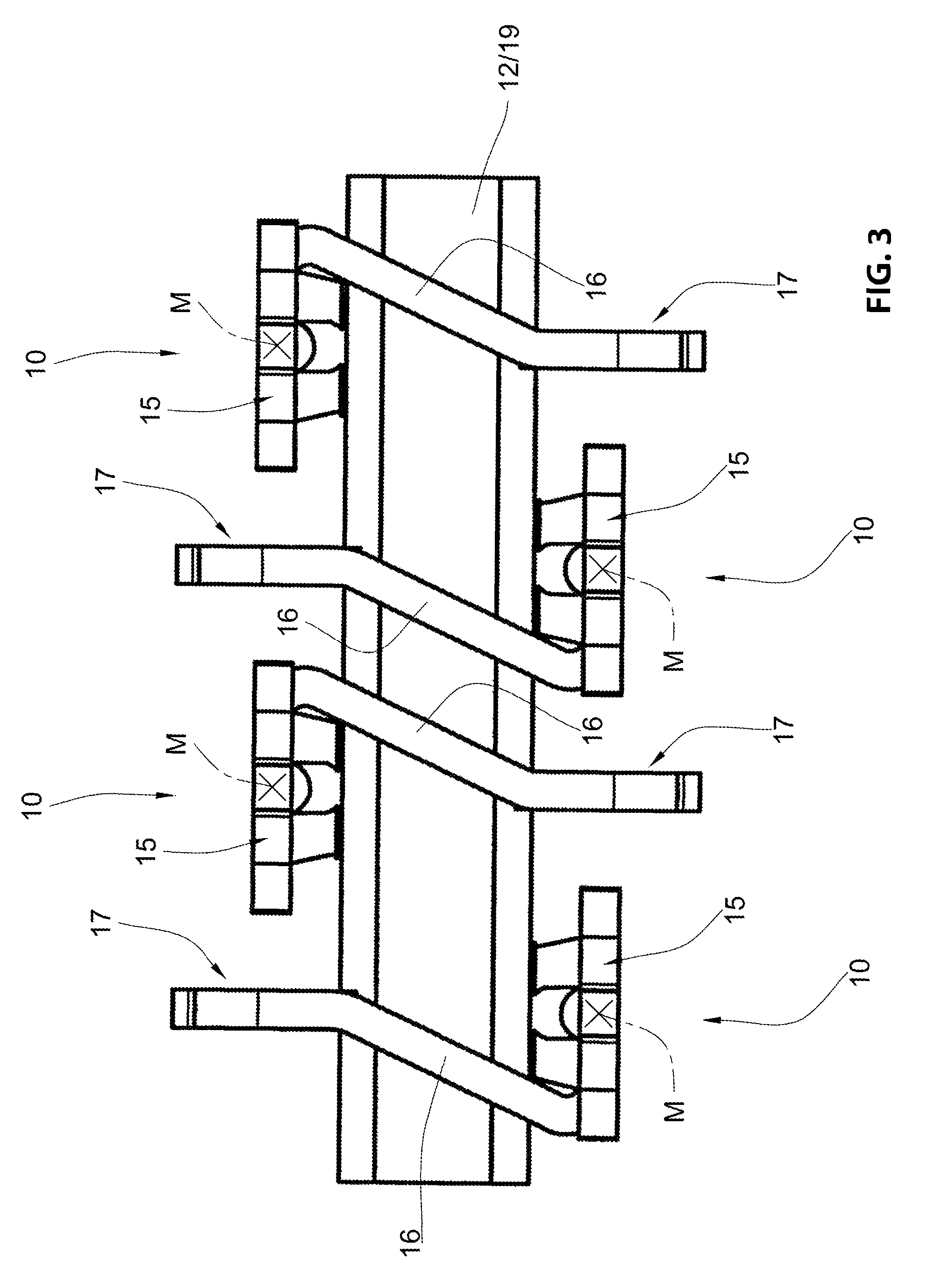
[0031]In the figures, an insertion contact according to the invention is designated with the reference numeral 10. The insertion contact 10 is illustrated by itself in FIGS. 1 and 2. It includes a contact arm 11 whose bottom side oriented towards a contact support 12 forms a contact protrusion 13. A connection member 14 configured as a cutting fork 15 is arranged at an end of the contact arm 11 that is oriented away from the contact protrusion 13. A connection arm 16 is attached laterally at the contact arm 11, thus in a transition portion to the connection member 14, and supports the support arm 17. The support arm 17 extends parallel to a longitudinal central axis M of the contact arm 11 and is arranged offset and below the contact arm 11 through the connection arm 16. At its free end, the support arm 17 includes a support protrusion 18 which is oriented towards the contact arm 11.

[0032]It is apparent from FIGS. 1 and 2 that the insertion contact 10 is configured as a stamped and ...


PUM


Abstract

The invention relates to an insertion contact for arrangement at a contact support including an opposite contact, the insertion contact including a contact arm which contacts a first contact surface of an opposite contact in an electrically conductive manner which opposite contact is arranged on a top side of a contact support; a support arm which contacts a bottom side of the contact support; and a connection arm which arranges the contact arm at the support arm, wherein the contact arm and / or the support arm is deflectable in a spring elastic manner, wherein the insertion contact includes a connection member for connecting a conductor, wherein the insertion contact is configured as a stamped component. It is an object of the invention to provide insertion contacts which facilitate reducing grid pitches of plug connectors, in particular according to Rast 2.5 standard, while maintaining predetermined technical specifications.

Description

RELATED APPLICATIONS[0001]This application claims priority from and incorporates by reference German patent application DE 10 2012 004 833.5, filed on Mar. 13, 2012.FIELD OF THE INVENTION[0002]The invention relates to an insertion contact for arrangement at a contact support including an opposite contact, the insertion contact including a first contact arm which contacts a first contact surface of the opposite contact arranged at a top side of the contact support and which first contact arm includes a support arm which contacts a bottom side of the contact support and a connection arm which arranges the contact arm at the support arm, wherein the contact arm and / or the support arm are deflectable in a spring elastic manner and wherein the insertion contact includes a connection member for connecting a conductor and wherein the insertion contact is configured as a stamped component.BACKGROUND OF THE INVENTION[0003]Insertion contacts of similar types are known from many applications. ...

Claims


Application Information

Patent Timeline
Patent Type & Authority Patents(United States)
IPC IPC(8): H01R4/48H01R12/50H01R12/72H01R13/11
CPCH01R23/7068H01R13/112H01R12/721H01R12/00
Inventor NEUMANN, WOLFGANGPFAFFENBACH, DIRKUMBACH, FRANK
Owner LUMBERG CONNECT
Why Eureka
Try Eureka