Eureka AIR delivers breakthrough ideas for toughest innovation challenges, trusted by R&D personnel around the world.

Optical fiber reel module and winding method therefor

a technology of optical fiber and reel module, which is applied in the direction of optical elements, instruments, optical waveguide light guides, etc., can solve the problems of high cost, deformation and/or damage of the coating of er doped optical fiber b>4/b>, and inability to adjust the high-precision amplification characteristic, so as to achieve the effect of reducing stress and high-precision amplification characteristic adjustmen

Inactive Publication Date: 2006-02-02
ARIMA TADAO
View PDF14 Cites 9 Cited by
  • Summary
  • Abstract
  • Description
  • Claims
  • Application Information

AI Technical Summary

Benefits of technology

[0010] It is therefore an object of the present invention to provide a rare-earth doped optical fiber module which can relieve the stress generated in winding a rare-earth doped optical fiber, thereby allowing high-precision adjustment of the amplification characteristic.
[0014] In accordance with another aspect of the present invention, there is provided a manufacturing method for a rare-earth doped optical fiber module, including the steps of setting a resin reel having elasticity on a metal reel whose diameter is changeable between a first diameter and a second diameter larger than the first diameter; increasing the diameter of the metal reel to the second diameter to thereby increase the diameter of the resin reel; winding a rare-earth doped optical fiber around the resin reel; decreasing the diameter of the metal reel to the first diameter; and removing the resin reel having the rare-earth doped optical fiber from the metal reel.

Problems solved by technology

Accordingly, the loss contributing to the amplification characteristic of the Er doped optical fiber 4 itself becomes unclear, so that the adjustment of high-precision amplification characteristic is impossible.
While another metal reel whose diameter is adjustable is used, such a metal reel is complicated in structure and it is therefore costly.
Accordingly, there is a possibility that the coating of the Er doped optical fiber 4 may be deformed and / or damaged.
Further, in adjusting the length of the Er doped optical fiber 4 or in splicing the single-mode optical fibers 12 to the opposite ends of the Er doped optical fiber 4, it is necessary to once remove the bundling tubes 14 and to bundle the Er doped optical fiber 4, so that the operation becomes troublesome.

Method used


Image

  • Optical fiber reel module and winding method therefor
  • Optical fiber reel module and winding method therefor
  • Optical fiber reel module and winding method therefor

Examples


Embodiment Construction

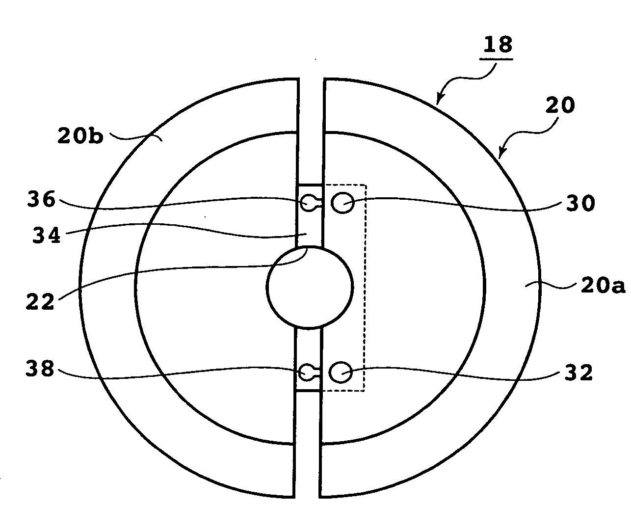
[0025] Referring to FIG. 4, there is shown a sectional view of an EDF module 16 according to a first preferred embodiment of the present invention in the condition that the EDF module 16 is mounted on a metal reel 18. FIG. 5 is a cross section taken along the line V-V in FIG. 4. The metal reel 18 is composed of a first segment 20 having a center hole 22 and a second segment 24 having a shaft 26 inserted in the center hole 22 of the first segment 20. A resin reel 28 having elasticity is mounted on the metal reel 18. The resin reel 28 is formed of silicone rubber, fluororubber, or soft polyvinyl carbazole (PVC), for example. The resin reel 28 is fabricated by using a mold so that the outer diameter of the bottom of the resin reel 28 becomes 60 mm.

[0026] As shown in FIG. 6, the first segment 20 of the metal reel 18 is composed of a first semicircular reel 20a and a second semicircular reel 20b. A pair of pins 30 and 32 are fixed to the first semicircular reel 20a. The second semicircu...


PUM

PropertyMeasurementUnit
outer diameteraaaaaaaaaa
lengthaaaaaaaaaa
wavelengthaaaaaaaaaa

Abstract

A optical fiber reel module including a reel having a continuous outer circumference and an optical fiber wound around the reel. The optical fiber reel module further includes an adjustable diameter between a first length and a second length and after an optical fiber is wound around the reel.

Description

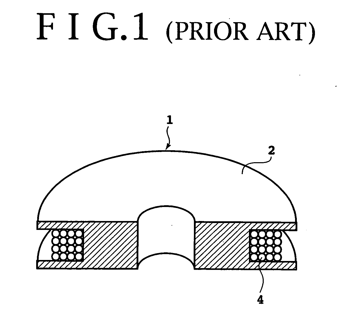
[0001] This application is a divisional of U.S. application Ser. No. 10 / 928,854 filed on Aug. 27, 2004 and claims priority from International PCT Application NO. PCT / JP02 / 03929, filed Apr. 19, 2002, the contents of which are herein wholly incorporated by reference.BACKGROUND OF THE INVENTION [0002] 1. Field of the Invention [0003] The present invention relates generally to an optical fiber module and winding method therefor, and more particularly to an optical fiber reel module and a winding method therefor. [0004] 2. Description of the Related Art [0005] An optical communication system using an optical amplifier for directly amplifying an optical signal has become general, and an EDF module is used as a basic component of such an optical amplifier having an optical amplifying function. FIG. 1 shows an EDF module 1 in the related art. As shown in FIG. 1, the EDF module 1 is configured by winding an Er doped optical fiber 4 around a metal reel 2. By adjusting the length of the Er dop...

Claims


Application Information

Patent Timeline
Patent Type & Authority Applications(United States)
IPC IPC(8): G02B6/00G02B6/36G02B6/44H01S3/067
CPCG02B6/14H01S3/06704G02B6/4457
Inventor ARIMA, TADAO
Owner ARIMA TADAO
Why Eureka
Eureka Blog
Learn More