
Vehicle-mounted control system and method for an internal combustion engine

a control system and engine technology, applied in electrical control, ignition automatic control, tractors, etc., can solve the problems of preventing the operation of the internal combustion engine, detecting erroneously, and preventing the internal combustion engine from operating

Active Publication Date: 2006-01-26
HONDA MOTOR CO LTD
View PDF8 Cites 12 Cited by
  • Summary
  • Abstract
  • Description
  • Claims
  • Application Information

AI Technical Summary

Benefits of technology

[0010] The present invention provides a control system and method for a vehicle having an internal combustion engine. It is an object of the present invention to provide a vehicle-mounted internal combustion engine controller that can appropriately stop the internal combustion engine in accordance with the operational state of the internal combustion engine.
[0016] Therefore, when the vehicle body inclination angle is greater than a predetermined angle, the internal combustion engine can be properly stopped in accordance with the operational state.
[0017] As far as an appropriate threshold stop time setting is defined for an operational state arising after the initial startup state, it is possible to prevent the internal combustion engine from coming to a stop when a leftward, rightward, or other vehicle body inclination is detected erroneously.
[0022] According to a sixth aspect of the present invention, the cutoff mechanism may stop the operation of the vehicle-mounted internal combustion engine by varying the fuel injection timing or the ignition timing from the normal timing thereof.

Problems solved by technology

Therefore, the inclination sensor may erroneously detect an undue vehicle body inclination that is greater than the actual one.
Therefore, the threshold stop time setting defined in JP-A No. 68062 / 2002 may unexpectedly stop the operation of the internal combustion engine depending on its operational state.

Method used


Image

  • Vehicle-mounted control system and method for an internal combustion engine
  • Vehicle-mounted control system and method for an internal combustion engine
  • Vehicle-mounted control system and method for an internal combustion engine

Examples


Embodiment Construction

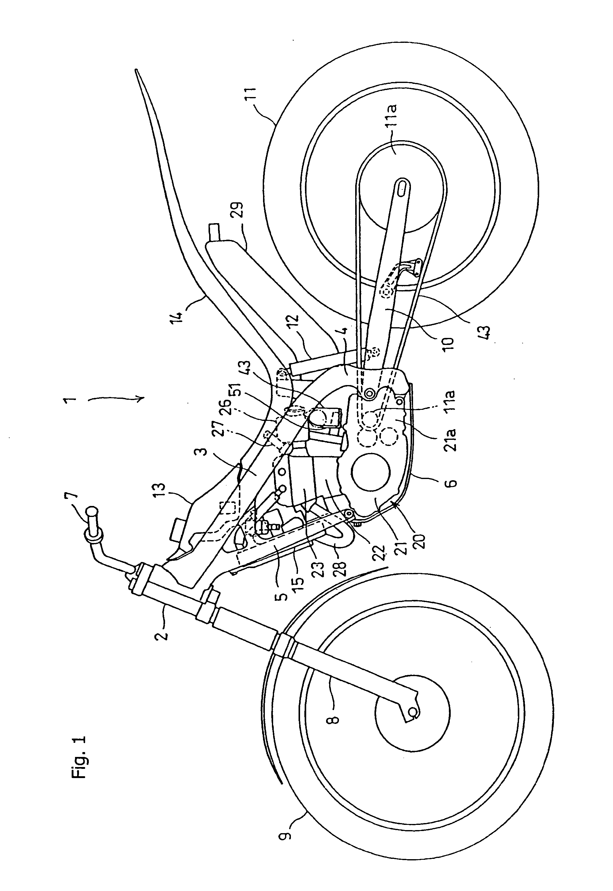
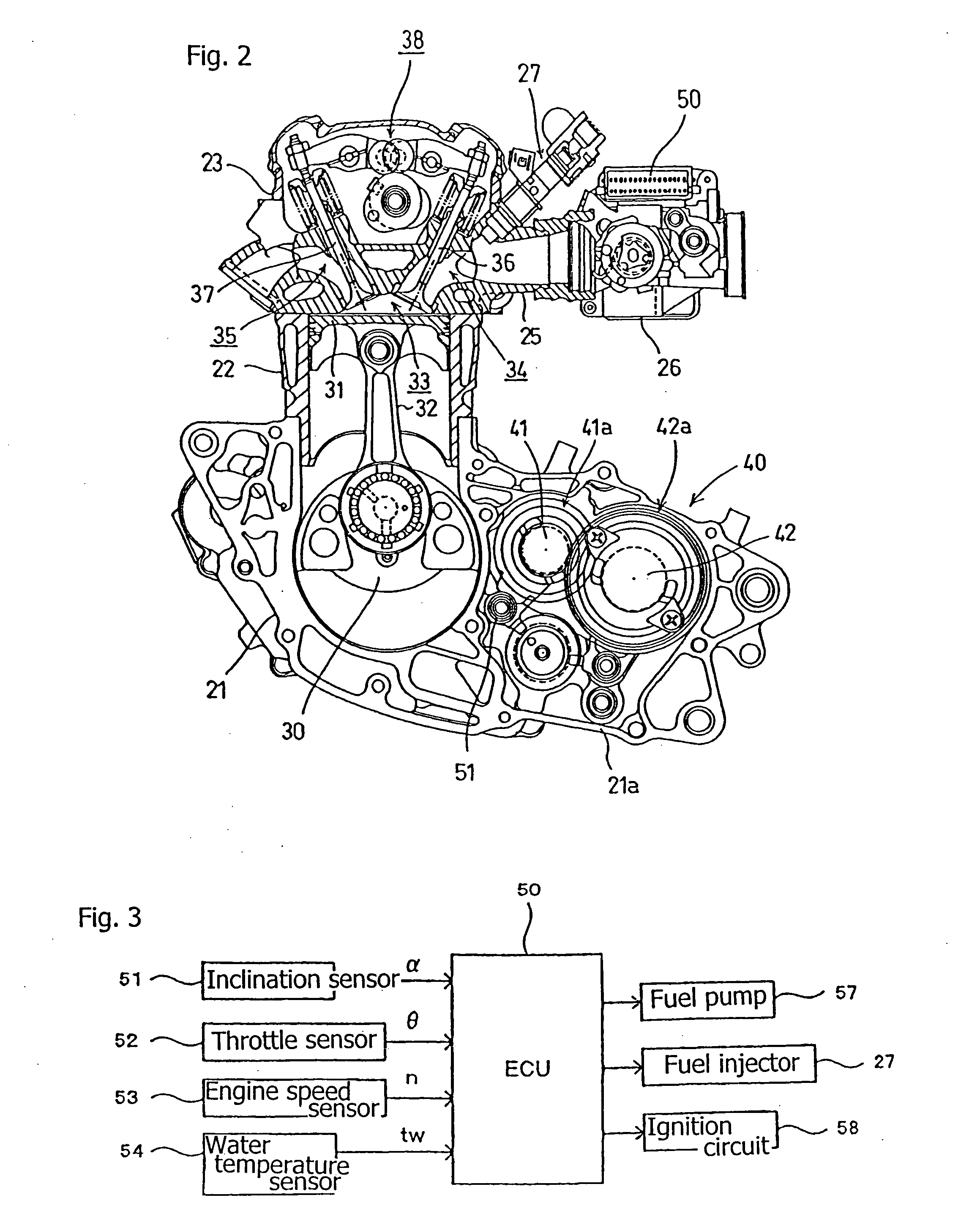
[0029] A selected illustrative embodiment of the present invention will now be described, with reference to FIGS. 1 to 4.

[0030] The present embodiment applies to an off-road motorcycle 1, sometimes referred to as a dirt bike. The motorcycle 1 includes a main frame 3, a center frame 4, and a down frame 5. The main frame 3, which is attached to a head pipe 2, is sloped downward slightly and rearward from the head pipe, and is forked into right- and left-hand parts. The center frame 4 is integrally attached to the rear of the main frame 3 and extends downwardly therefrom. The down frame 5, which is also attached to the head pipe 2, is sloped significantly downward and rearward below the main frame, and the down frame is also forked into right- and left-hand parts.

[0031] An internal combustion engine 20 is suspended between the down frame 5, which is at the front of the motorcycle 1, and the center frame 4, which is at the rear of the motorcycle 1. The underside of the internal combus...


PUM


Abstract

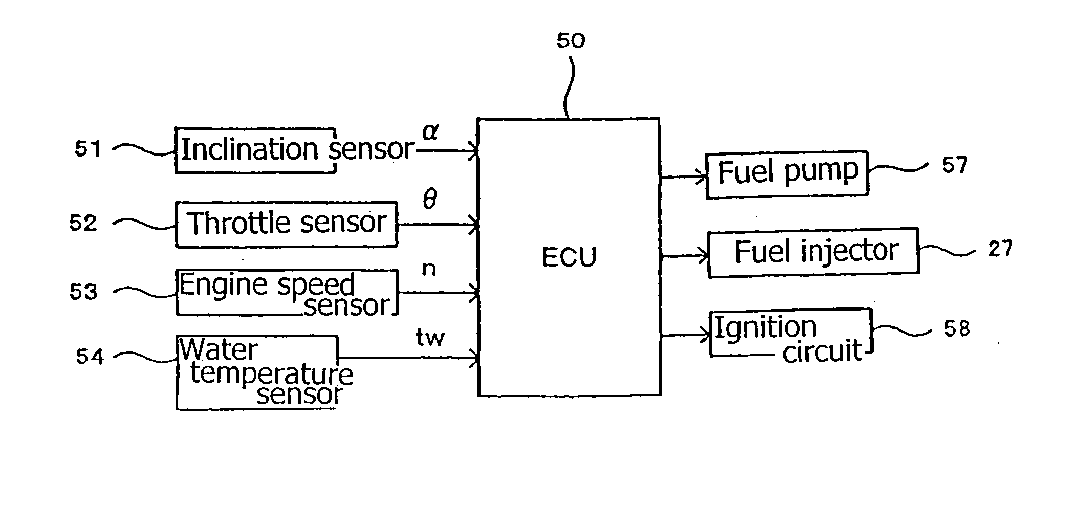
A vehicle-mounted internal combustion engine controller is provided that can properly stop an internal combustion engine in accordance with an operational state no matter whether a vehicle body is inclined. The vehicle-mounted internal combustion engine controller comprises an inclination sensor for detecting vehicle body inclination; a mechanism for determining the operational state of a combustion engine; and a controller for stopping the operation of the combustion engine in accordance with a vehicle body inclination and an operational state. The cutoff mechanism stops the operation of the vehicle-mounted internal combustion engine when it is judged that a vehicle body inclination angle a detected by the inclination sensor is greater than a predetermined angle A for a greater or equal period of time as a threshold stop time T1, T2 setting, which varies with the operational state determined by the operational state sensor.

Description

CROSS-REFERENCE TO RELATED APPLICATIONS [0001] The present invention claims priority under 35 USC 119 based on Japanese patent application No. 2004-213317, filed on Jul. 21, 2004. The subject matter of this priority document is incorporated by reference herein. BACKGROUND OF THE INVENTION [0002] 1. Field of the Invention [0003] The present invention relates to a vehicle-mounted engine control system and method for an internal combustion engine, in which the system includes a control unit and an inclination sensor for detecting a vehicle body inclination. [0004] 2. Description of the Background Art [0005] The applicant of the present invention previously filed an application for a patent, JP-A No. 68062 / 2002, to disclose a motorcycle-mounted internal combustion engine controller that includes an inclination sensor for detecting a vehicle body inclination. [0006] The controller disclosed in JP-A No. 68062 / 2002 includes an inclination sensor. A plumb bob is suspended within a case, whi...

Claims


Application Information

Patent Timeline
Patent Type & Authority Applications(United States)
IPC IPC(8): G06F19/00B62J99/00F02D17/04F02D29/02F02D45/00F02P5/15
CPCB60K28/14B60W2510/0676B60W2520/18B62M7/00B60W2710/0616B60Y2200/12B62J27/00B60W2550/12B60W2555/20
Inventor KAKINUMA, HIROYUKI
Owner HONDA MOTOR CO LTD
Learn More