
Laser burst boosting method and apparatus

a laser burst and boosting technology, applied in lasers, laser cooling arrangements, laser details, etc., can solve problems such as heat generation of the gain medium

Active Publication Date: 2006-01-26
LUMENTUM OPERATIONS LLC
View PDF50 Cites 28 Cited by
  • Summary
  • Abstract
  • Description
  • Claims
  • Application Information

AI Technical Summary

Benefits of technology

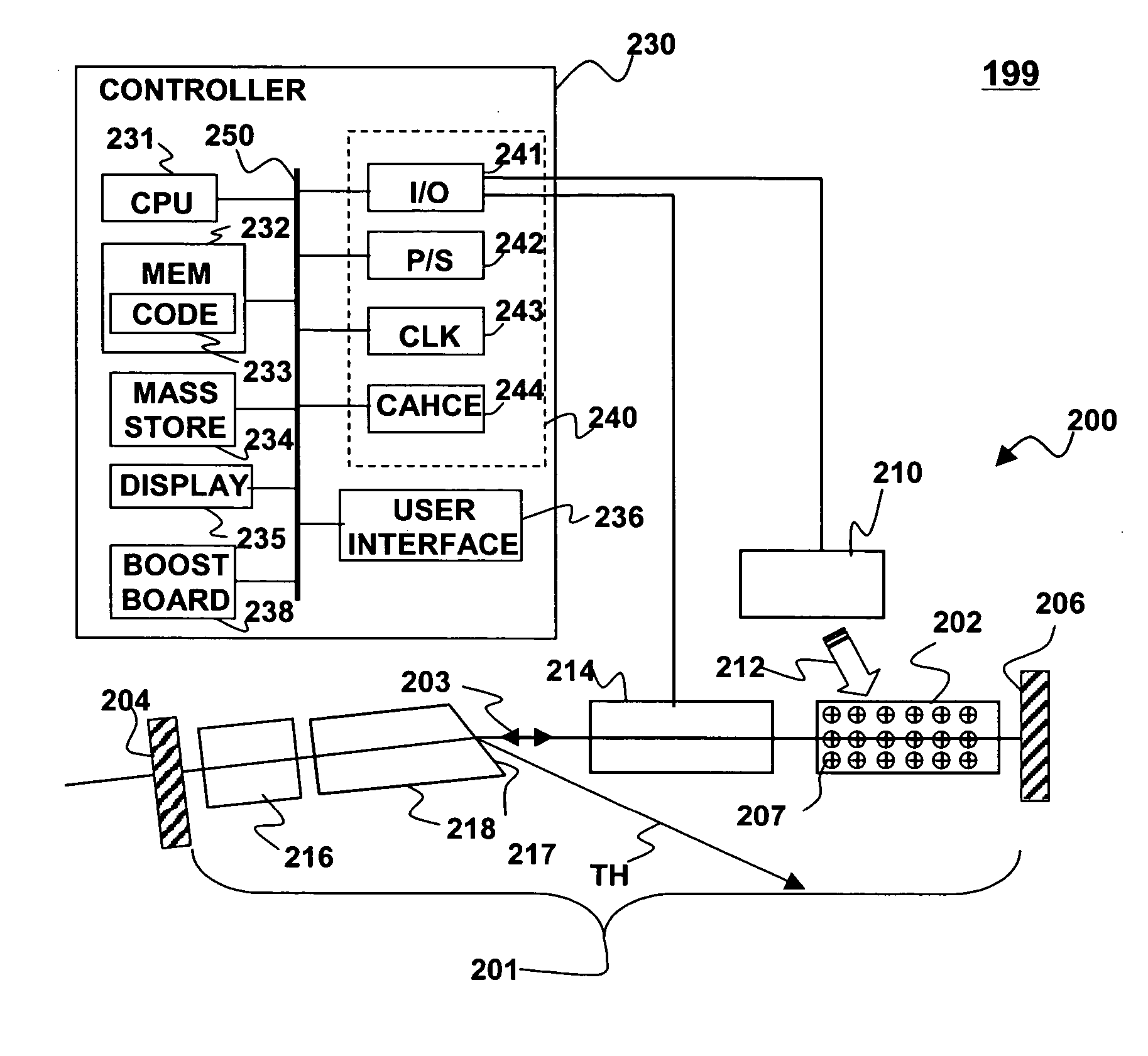
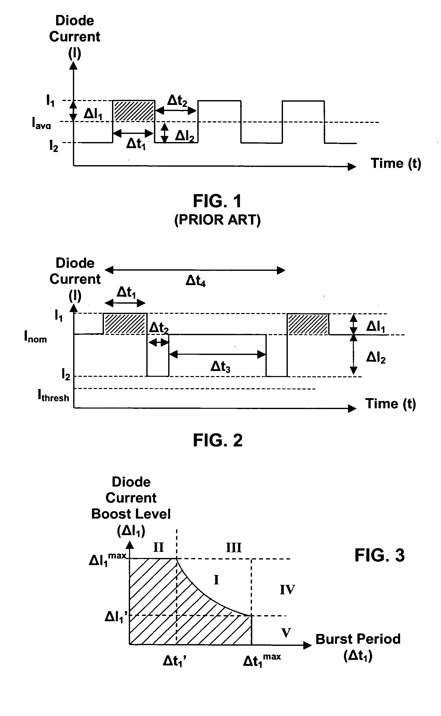
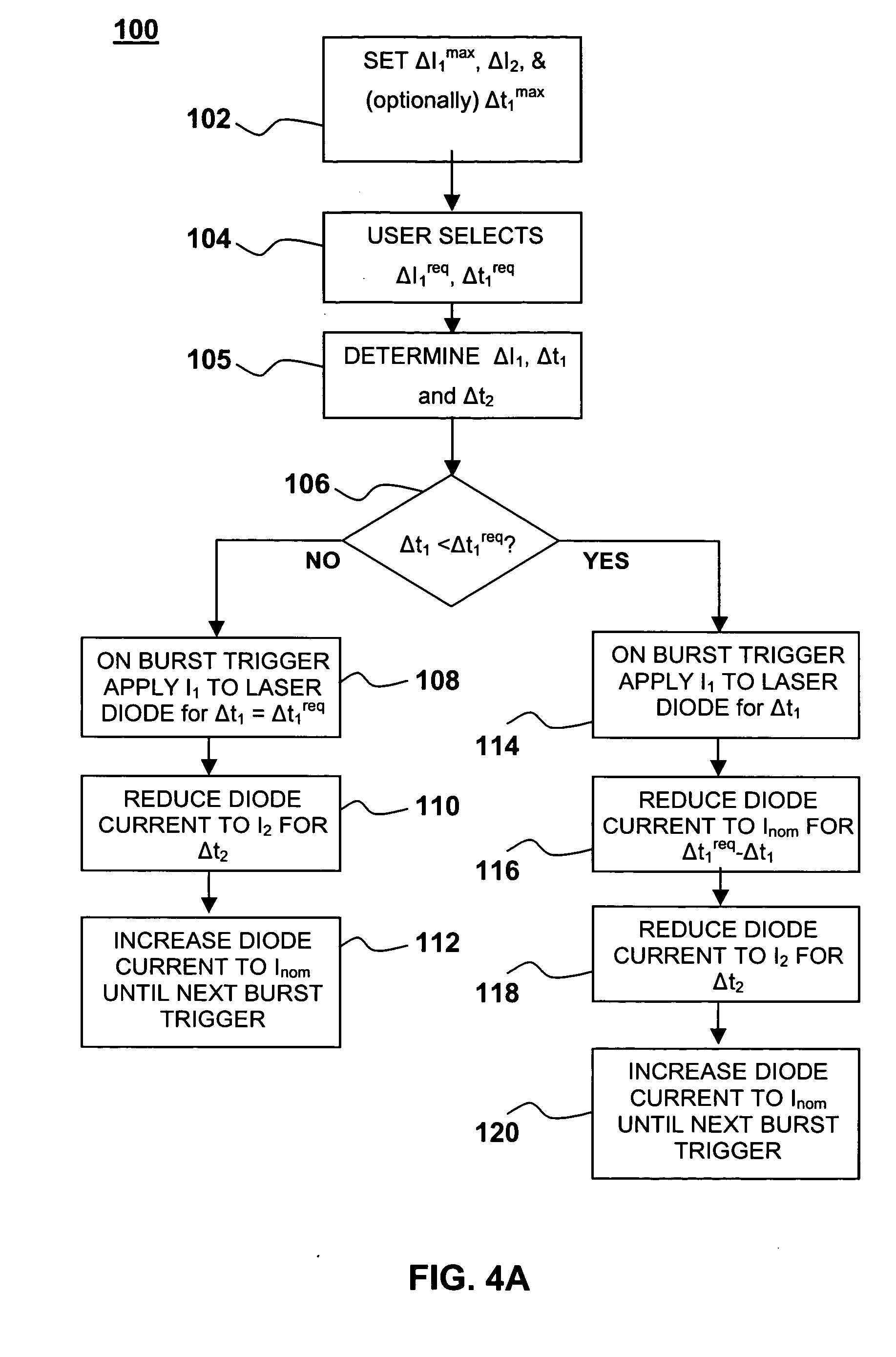
[0006] Certain embodiments of the present invention implement thermal management through pulsed operation of a diode-pumped laser involving three levels of diode current. A pulse of current is applied to the diode at a first current level for a first time interval. The first current level exceeds a nominal current value by an amount ΔI1. The diode current is reduced to a second current level for a second time interval. The nominal current exceeds the second current level by an amount ΔI2. To balance the thermal load on the laser diode and on the diode-pumped laser gain medium, an integral of ΔI1 over the time the first interval is approximately equal in magnitude to an integral of ΔI2 over the second interval. In addition, in a preferred embodiment, the first and second time intervals are similar to or (ideally) less than a maximum time interval that depends on a thermal relaxation time associated with the laser diode. After applying the pulse of current at the first current level, and before or after reducing the current to the second level, the nominal current is applied to the laser diode for a third time interval before applying another pulse of current to the laser diode.

Problems solved by technology

The burst of energy results in heating of the gain medium.

Method used


Image

  • Laser burst boosting method and apparatus
  • Laser burst boosting method and apparatus
  • Laser burst boosting method and apparatus

Examples


Embodiment Construction

[0016] Although the following detailed description contains many specific details for the purposes of illustration, anyone of ordinary skill in the art will appreciate that many variations and alterations to the following details are within the scope of the invention. In the mathematical derivations described below certain assumptions have been made for the sake of clarity. These assumptions should not be construed as limitations on the invention. Accordingly, the exemplary embodiments of the invention described below are set forth without any loss of generality to, and without imposing limitations upon, the claimed invention.

Glossary:

[0017] As used herein:

[0018] The article “A”, or “An” refers to a quantity of one or more of the item following the article, except where expressly stated otherwise.

[0019] Cavity refers to an optical path defined by two or more reflecting surfaces along which light can reciprocate or circulate. Objects that intersect the optical path are said to b...


PUM


Abstract

Methods and apparatus for managing thermal loads on a laser gain medium and for boosting the output power of a diode pumped laser are disclosed. The short-term average pumping power to the gain medium is increased, to provide a burst of pumping energy to the laser gain medium. A subsequent short-term reduction in the average pumping power then allows the gain medium to cool to a desired state steady level. The average pumping power is then increased to maintain this steady state level until the next burst is desired. For example, a pulse of current may be applied to a laser diode at a first current level I1 for a first time interval Δt1, where I1 exceeds a nominal current value Inom by an amount ΔI1. The current to the laser diode is reduced to a second current level I2 for a second time interval Δt2, where Inom exceeds I2 by an amount ΔI2. To balance the thermal load on the diode an integral of ΔI1 over the time Δt1 is approximately equal in magnitude to an integral of ΔI2 over the time Δt2. After applying the pulse of current at the first current level I1, and before or after reducing the current to the second level I2, the nominal current is applied to the laser diode for a third time interval Δt3.

Description

FIELD OF THE INVENTION [0001] This invention generally relates to lasers and more particularly to increasing the power of a laser during pulse-burst operation. BACKGROUND OF THE INVENTION [0002] Many high-powered laser applications use a laser diode as a source of pump radiation for the gain medium in a laser system. Such laser diodes are semiconductor devices that produce coherent radiation when an electric current passes through the diode. Certain high-powered applications, such as laser drilling, call for delivery of the laser output radiation in bursts of pulses lasting e.g., a few milliseconds or less. During laser pulse bursts, the current to the laser diode may be modulated to boost the current to a high level for a short period time before returning to a low level. The high level of current during the burst provides a high power that, if maintained for too long, would tend to overheat and / or degrade the laser diode and / or the diode-pumped laser performance. Consequently, the...

Claims


Application Information

Patent Timeline
Patent Type & Authority Applications(United States)
IPC IPC(8): H01S3/04
CPCH01S3/094076H01S3/0941H01S3/1024H01S3/08072H01S3/109H01S5/06216H01S5/0622H01S3/1028
Inventor ADAMS, FRANK J.ARBORE, MARK A.WIECHMANN, WERNER H.
Owner LUMENTUM OPERATIONS LLC
Learn More