
Method and device for eliminating connecting webs between ice cubes

Inactive Publication Date: 2006-01-26
NIDEC MOTOR CORP
View PDF34 Cites 13 Cited by
  • Summary
  • Abstract
  • Description
  • Claims
  • Application Information

AI Technical Summary

Benefits of technology

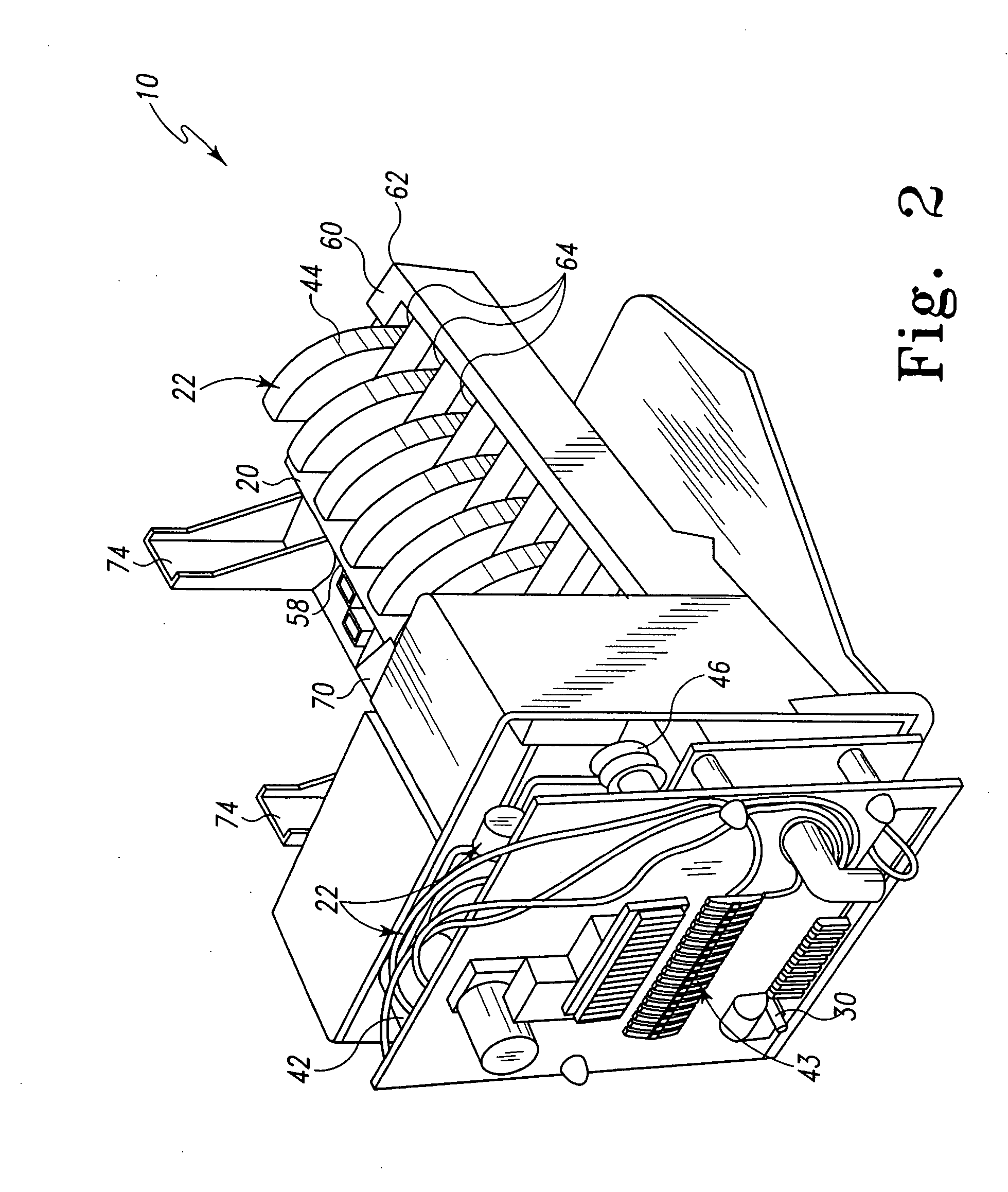
[0006] Icemakers have a series of compartments in an ice tray that are filled with water. As the water cools, it begins to freeze. The traditional method of evenly filling the water into each compartment of the ice tray 2020 has been to provide a slot 2090 formed in a dividing wall 2080 between compartments 2066 that allows the water to move freely between the compartments 2066. Sufficient water is provided to the tray 2020 to allow the water level in each compartment 2066 to be higher than the bottom of the slot 2090 so that gravity can cause the water to level out. During freezing the water remaining in the slots 2090 after filling the compartments 2066 forms a web or bridge between cubes formed in each compartment 2066. After the cubes are frozen, the ejector arm is rotated so that a finger extends into each compartment 2066 to urge the cube formed therein out of the ice compartment 2066.
[0008] It would be desirable to eliminate the web or bridge between ice cubes formed in an automatic icemaker. The elimination of the web or bridge would provide more aesthetically pleasing ice cubes. Additionally, the elimination of the web or bridge may reduce the force that the fingers of the ejector arm are subjected to during ejection of the ice cubes as the ejector arm. Elimination of the ice bridge would also reduce the amount of ice chips formed during the ejection process reducing the tendency of the ice cubes to fuse together in the bin.

Problems solved by technology

Nevertheless, the ejector arm often breaks the web or bridge between cubes during the ejection process forming ice chips that can induce the ice cubes to fuse together in the ice bin.
Also, remnants of the web or bridge typically remain on the cube forming a less aesthetically pleasing cube.

Method used


Image

  • Method and device for eliminating connecting webs between ice cubes
  • Method and device for eliminating connecting webs between ice cubes
  • Method and device for eliminating connecting webs between ice cubes

Examples


Embodiment Construction

[0045] For the purposes of promoting an understanding of the principles of the invention, reference will now be made to the embodiments illustrated in the drawings and described in the following written specification. It is understood that no limitation to the scope of the invention is thereby intended. It is further understood that the present invention includes any alterations and modifications to the illustrated embodiments and includes further applications of the principles of the invention as would normally occur to one skilled in the art to which this invention pertains.

[0046] The disclosed icemaker assembly 10 eliminates ice webs or bridges between ice cubes by providing an ice tray 20 with compartments 66 having lateral side walls 100, 94 and 92, 102 of sufficient height to permit insertion of an object into each compartment 66 during or after filling and overflow of the compartment 66 and removal of the object from each compartment 66 after filling and overflow of the comp...


PUM


Abstract

A method and device for making ice is disclosed. The icemaker assembly comprises an ice tray and an ice ejector. The ice tray has at least (i) a first ice forming compartment defining a first space, and (ii) a second ice forming compartment defining a second space. The ice ejector is positionable at a first position and a second position. The ice ejector has at least (i) a first ejector member, and (ii) a second ejector member. When the ice ejector is positioned at the first position, (i) the first ejector member is positioned in the first space and in contact with a first quantity of water, (ii) the second ejector member is positioned in the second space and in contact with a second quantity of water, and (iii) the first quantity of water is positioned in fluid communication with the second quantity of water. When the ice ejector is positioned at the second position, (i) the first ejector member is spaced apart from both the first space and the first quantity of water, (ii) the second ejector member is spaced apart from both the second space and the second quantity of water, and (iii) the first quantity of water is isolated from fluid communication with the second quantity of water.

Description

CROSS REFERENCE [0001] Cross reference is made to co-pending U.S. patent applications Ser. No. 10 / ______ (Attorney Docket No. 1007-0574), entitled Method and Device for Stirring Water During Icemaking and Ser. No. 10 / ______ (Attorney Docket No. 1007-0579), entitled Method and Device for Producing Ice Having a Harvest-facilitating Shape, which are assigned to the same assignee as the present invention, and which are filed concurrently herewith, the disclosure of which are hereby incorporated by reference in their entirety.BACKGROUND AND SUMMARY [0002] This invention relates to household icemakers and more particularly to icemakers having a tray including multiple compartments filled by introducing water into a single compartment which overflows into adjacent compartments to fill compartments to similar levels. [0003] Refrigerators with icemakers are a popular consumer item, and most side-by-side refrigerator / freezers have icemakers installed as standard items. In a typical refrigerat...

Claims


Application Information

Patent Timeline
IPC IPC(8): F25C1/00F25C5/18
CPCF25C1/04F25C5/08F25C2700/06F25C2700/04F25C2400/10F25C2305/024
Inventor TREMBLAY, DENNIS D.SLOCUM, LAURENCE S.COLE, RONALD E.
Owner NIDEC MOTOR CORP
Learn More