
Method and apparatus for large signal detection passive infrared sensor applications

a passive infrared sensor and large signal technology, applied in the field of intrusion detectors, can solve the problems of false alarm signal, false alarm signal, and blinding of the processing circuit to the upper bound, and achieve the effect of affecting the performance of the detector

Active Publication Date: 2006-01-19
HONEYWELL INT INC
View PDF4 Cites 8 Cited by
  • Summary
  • Abstract
  • Description
  • Claims
  • Application Information

AI Technical Summary

Benefits of technology

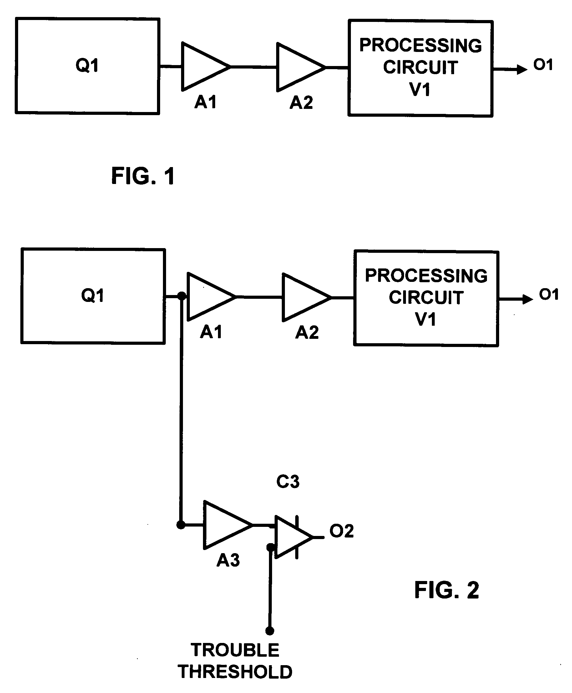
[0003] Still another object of the invention is to provide a method and apparatus which when such large signals are detected, the processing logic will output a trouble signal to the alarm control panel.
[0004] Yet another object invention is to provide a method and apparatus that will send a trouble signal to inform the central station that the sensor has detected a disturbance within the detector's field of view that will impair the detector's performance.

Problems solved by technology

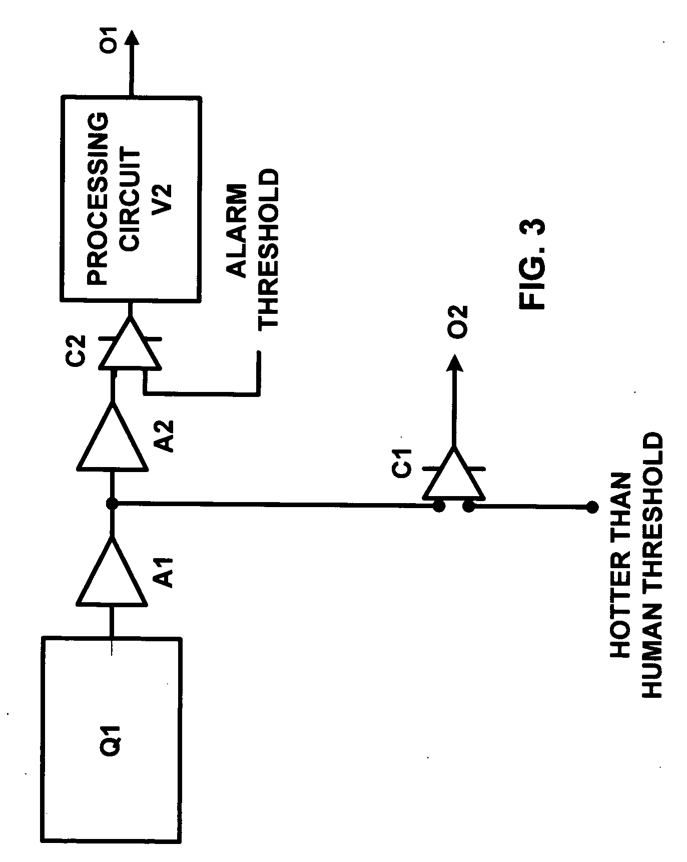
One of the major drawbacks with this arrangement is that an alarm signal is generated when the minimum threshold is exceeded regardless of the source of the signal For example, an active space heater in the detector's field of view will generate a signal approximately ten times larger than that of an intruder.
Unfortunately, the processing circuit is blind to the upper bound of the signal and generates a false alarm signal.

Method used


Image

  • Method and apparatus for large signal detection passive infrared sensor applications
  • Method and apparatus for large signal detection passive infrared sensor applications
  • Method and apparatus for large signal detection passive infrared sensor applications

Examples


Embodiment Construction

[0018] There are a variety of central station systems intended for homeowners, business owners, and other potential targets for burglary, that are monitored by a central station. These systems are vastly superior to older systems that merely sound a bell or alarm. They have also largely replaced systems that were tied in directly to the local police station. As the use of burglar alarms increased, the local police departments began turning down more and more requests to be “hooked-up.” As a result, there became a demand for central stations, or companies whose specialty it was to simply monitor burglar alarms. Most police departments will still allow banks and large jewelry stores a direct link to the police station, but as a rule, homeowners are excluded. So as the demand for security has risen, many guard agencies and burglar alarm installers have begun to offer centralized monitoring as an option for their clients.

[0019] When such systems are installed, it is common for them to ...


PUM


Abstract

Apparatus for passive infrared sensing of an intruder that discriminates between signals corresponding to a human target and much larger signals may include first and second IR sensors, at least a first amplifier having a first voltage operating range. The first amplifier may be connected to the first IR sensor and the apparatus may further include at least a second amplifier having a second voltage operating range. The second amplifier may also be connected to the first IR sensor and the apparatus may further include a comparator for comparing the respective outputs of the first and second amplifiers to predetermined values. The invention also includes the method for differentiating between a signal caused by human target and a signal caused by other much larger by IR sources which includes providing at least a first IR sensor, providing at least a first amplifier connected to the first IR sensor, providing a second amplifier connected to the first IR sensor having a second operating range, comparing the outputs of said first and second amplifiers to predetermined values to differentiate between the output from a sensor corresponding to the maximum signal for human target and a signal that is larger than the maximum signal from a human target.

Description

BACKGROUND OF THE INVENTION [0001] The invention relates to security systems and particularly to intrusion detectors that utilize a passive infrared sensor (PIR) to detect the presence of an intruder within the protected area by sensing the heat emitted by the intruder's body. The PIR sensor has a detector that outputs a signal that is proportional to the difference between the intruder's body temperature and the background temperature of the sensor's field of view. This signal is amplified to levels compatible with the sensor's processing logic. The processing logic contains a thresholding means and will output an alarm signal if a minimum threshold is exceeded. One of the major drawbacks with this arrangement is that an alarm signal is generated when the minimum threshold is exceeded regardless of the source of the signal For example, an active space heater in the detector's field of view will generate a signal approximately ten times larger than that of an intruder. Unfortunately...

Claims


Application Information

Patent Timeline
Patent Type & Authority Applications(United States)
IPC IPC(8): G01J5/02
CPCY10S250/01G08B13/19
Inventor ESKILDSEN, KENNETH G.
Owner HONEYWELL INT INC
Learn More