
Surge reduction bypass valve

a bypass valve and surge pressure technology, applied in the direction of drilling pipes, wellbore/well accessories, sealing/packing, etc., can solve the problems of increasing flow velocity, safety hazards, slippery rig floor, etc., and achieve the effect of reducing surge pressur

Active Publication Date: 2006-01-19
ALFORD RES +1
View PDF33 Cites 83 Cited by
  • Summary
  • Abstract
  • Description
  • Claims
  • Application Information

AI Technical Summary

Benefits of technology

[0019] In yet another aspect, embodiments of the present invention provide a diverter tool for reducing surge pressure when running casing into a wellbore comprising a tubular body having a longitudinal bore therethrough and first and second ends, and a by...

Problems solved by technology

Over-pressurizing the formation causes damage to the formation, jeopardizing production of hydrocarbons.
The upward flow velocity problem is exacerbated by the presence of the running string used to run each casing into the wellbore.
An uncontrolled flow of fluid from downhole causes fluid to flow onto the rig floor from downhole, making the rig floor slippery and a safety hazard.
Reducing the speed of running casings into the wellbore and cleaning up the rig floor increases the amount of time required to obtain a producing wellbore, thus increasing the cost of the wellbore.
A similar problem occurs when running casing into a wellbore formed in a delicate formation, regardless of whether a previous casing exists and regardless of whether the clearance between casings is small.
Running casing into a delicate formation could easily result in damage to the formation due to high downhole pressure caused by running the casing into the wellbore.
However, the hydrostatic pressure changes due to changes in depth; therefore, this diverter tool may not operate correctly when the wellbore is not a vertical wellbore (e.g., a deviated, lateral, directional, or horizontal wellbore).
However, sometimes while running the casing into the wellbore, the casing reaches an obstruction which prevents the casing from running further into the wellbore.
While the proposed diverter tool allows closure of the ports for possible circulation of fluid down through the casing to wash away an obstruction, the one-shot nature of the diverter tool does not allow fluid to flow out through the ports in the diverter tool again as the casing is further lowered into the wellbore subsequent to removal of the obstruction, again creating the problem of a surge of fluid upon further downward movement of the casing into the wellbore due to the absence of a functioning diverter tool.
Because the ports of the one-shot diverter tool cannot again be opened while the diverter tool is in the wellbore during the casing running operation, the possibility of formation damage is greatly increased.
Multiple run-ins of the casing and servicing of the diverter tool after its removal from the wellbore add time and thus cost to the formation of the wellbore.
This diverter tool is disadvantageous because the inner diameter of the diverter tool is restricted.
This proposed diverter tool is also a one-shot tool which only permits closing the ports once without removing the running string for servicing of the diverter tool causing the same problems encountered in the other proposed diverter tool mentioned above.

Method used


Image

  • Surge reduction bypass valve
  • Surge reduction bypass valve
  • Surge reduction bypass valve

Examples


Embodiment Construction

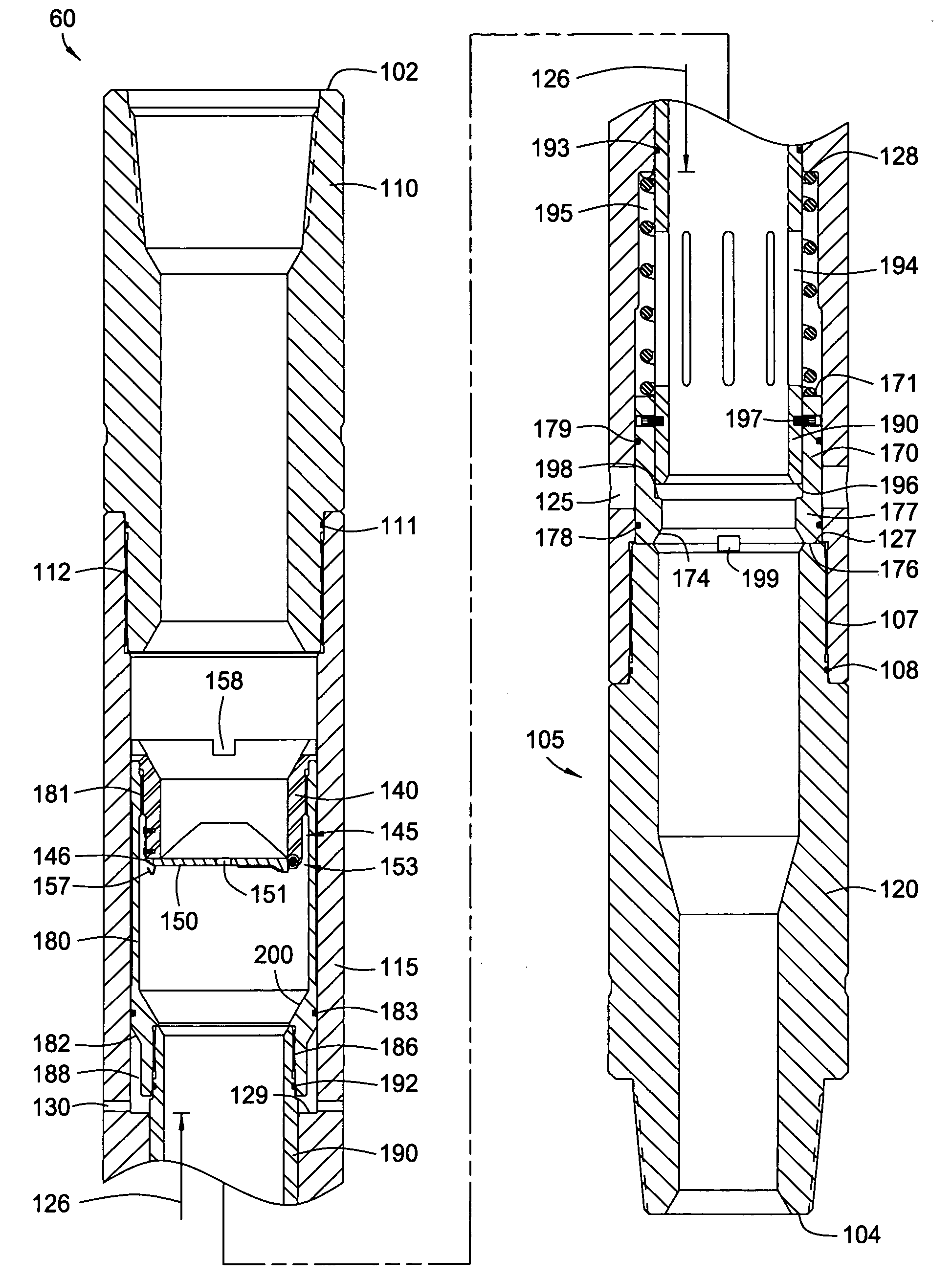
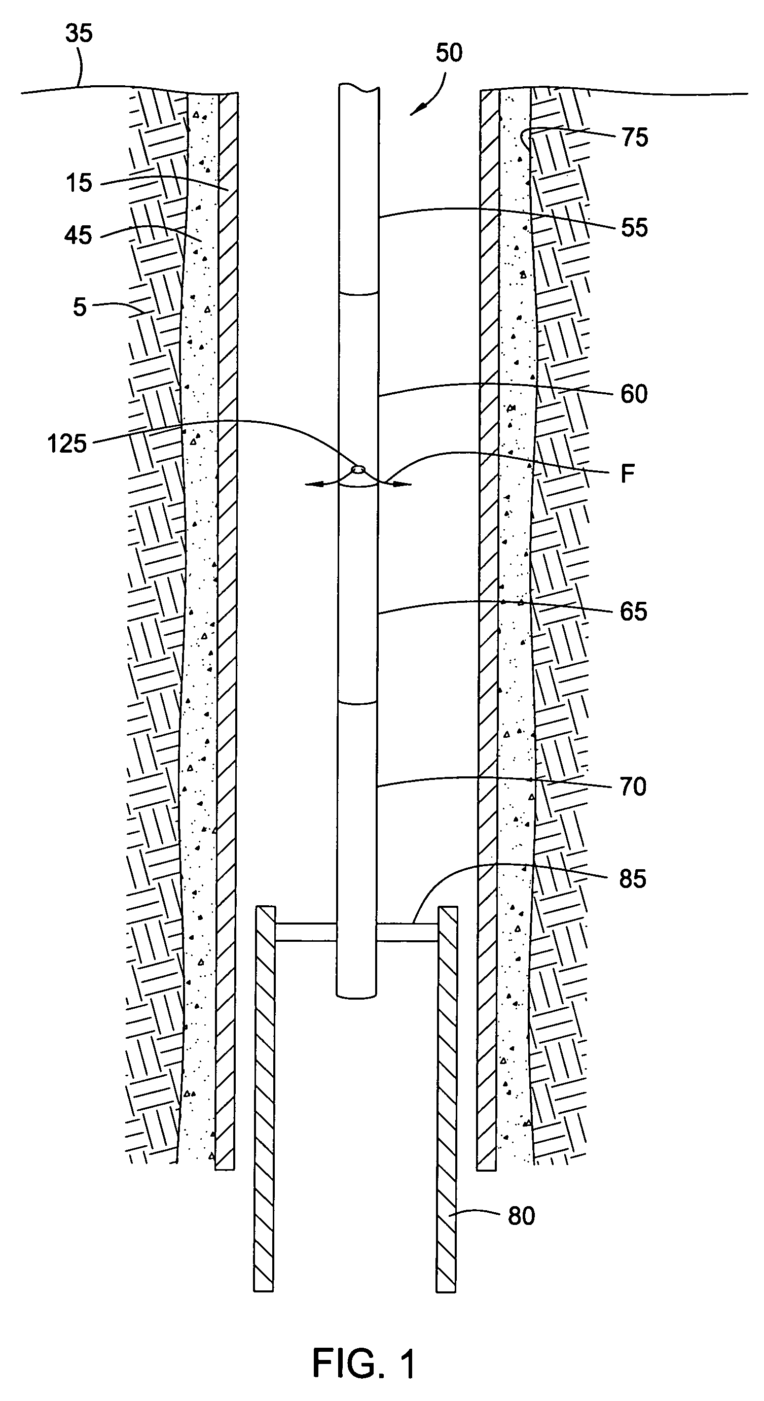
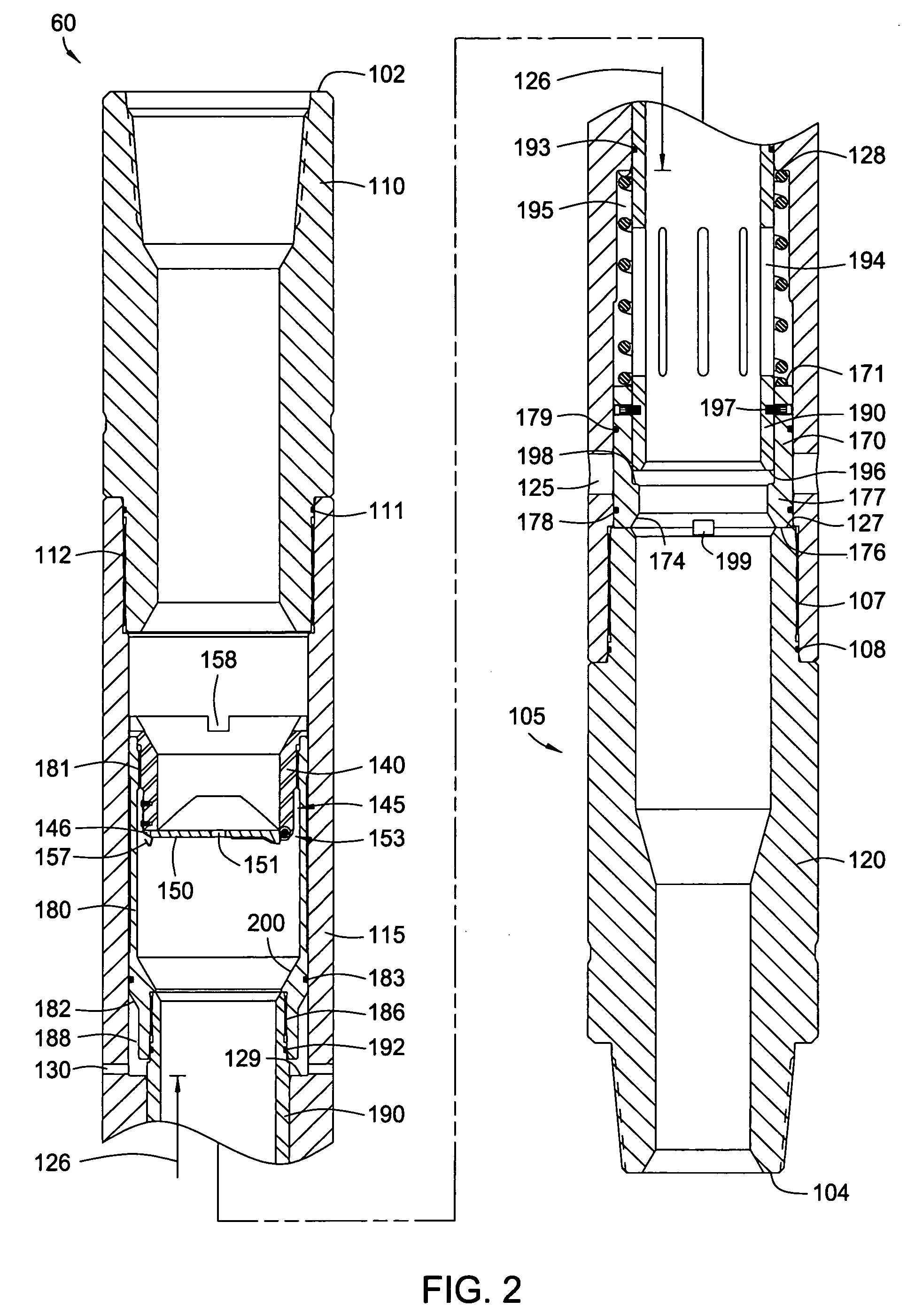
[0028] The present invention provides a diverter tool having a bypass valve for reducing surge pressure while running casing into the wellbore. The bypass valve is capable of automatically opening and closing multiple times while the casing is run into the wellbore without user intervention or activation beyond typical casing running procedures. This automatic opening and closing of the bypass valve allows the casing to be run into the wellbore at an increased speed as compared to other diverter tools because the probability and magnitude of damage to the formation is decreased. The diverter tool operates without restricting the bore of the running string or the diverter, thereby allowing full access through the inner diameter of the diverter tool. Moreover, the diverter tool does not require dropping or pumping any device into the tool to function the bypass valve during run-in of the casing. Advantageously, the diverter tool of the present invention provides an apparatus and metho...


PUM


Abstract

Methods and apparatus are provided for reducing surge pressure while running casing into a wellbore. The apparatus includes a running string for running casing having a diverter tool therein. The diverter tool has one or more bypass ports between its upper and lower end which are normally closed. In operation, the diverter tool is automatically cycled between the open and closed positions of the bypass ports during a casing running operation. A pressure event inside the diverter tool deactivates the cyclic opening and closing function of the bypass port.

Description

CROSS-REFERENCE TO RELATED APPLICATIONS [0001] This application claims benefit of U.S. Provisional Patent Application Ser. No. 60 / 588,463, filed Jul. 16, 2004, which application is herein incorporated by reference in its entirety.BACKGROUND OF THE INVENTION [0002] 1. Field of the Invention [0003] Embodiments of the present invention generally relate to running casing into a wellbore. More specifically, embodiments of the present invention relate to managing surge pressure while running casing into the wellbore. [0004] 2. Description of the Related Art [0005] To obtain hydrocarbon fluid production from the earth, a wellbore is drilled from the surface of the earth using a drill string. The drill string is a tubular body having a drill bit attached to its lower end for making a hole in the earth. After the drill string has drilled the wellbore to a first depth, the drill string is removed from the wellbore. [0006] Subsequent to removing the drill string from the wellbore, a first sect...

Claims


Application Information

Patent Timeline
IPC IPC(8): E21B43/32E21B33/12E21B21/10E21B34/00E21B43/10
CPCE21B21/103E21B2034/005E21B43/10E21B2200/06E21B2200/05
Inventor LOGIUDICE, MICHAELMARTENS, JAMES G.
Owner ALFORD RES
Learn More