
Control system, method, and program using rhythm pattern

Inactive Publication Date: 2006-01-19
PANASONIC CORP
View PDF0 Cites 26 Cited by
  • Summary
  • Abstract
  • Description
  • Claims
  • Application Information

AI Technical Summary

Benefits of technology

[0017] According to the above-described first aspect, an operation of each apparatus is controlled only by the user tapping a rhythm input section. Therefore, a control system which can control an operation of each apparatus using such small a number of input devices as possible (typically, one switch or sensor), is provided. Further, a control system without being affected by noise is provided. Further, the user can operate each apparatus only by inputting a rhythm pattern in accordance with a rhythm of a natural language, thereby providing a control system having satisfactory operability. Further, the user can be expected to acquire operations quickly.
[0077] Thereby, the control system can automatically recognize the end of inputting. Therefore, the user does not have to perform an operation for finishing inputting.

Problems solved by technology

The increased number of operating devices makes it difficult to operate the apparatus.
Also, it is difficult to arrange input devices supporting tens or hundreds of functions in a limited space.
The user cannot select a desired function by one-time operation.
These requirements are a barrier against the introduction of the system for the user who is bad with machines.
Systems employing speech recognition have a problem such that the speech recognition rate is impaired depending on the surrounding situation, such as surrounding noise, background music, the user's voice, the position of a microphone, or the like.
When the speech recognition rate is impaired, a desired function is not eventually performed.
Also, speech recognition requires a large-capacity memory and high computation speed.
Therefore, systems with a poor memory and low computation speed cannot achieve practical speech recognition speed.

Method used


Image

  • Control system, method, and program using rhythm pattern
  • Control system, method, and program using rhythm pattern
  • Control system, method, and program using rhythm pattern

Examples


first embodiment

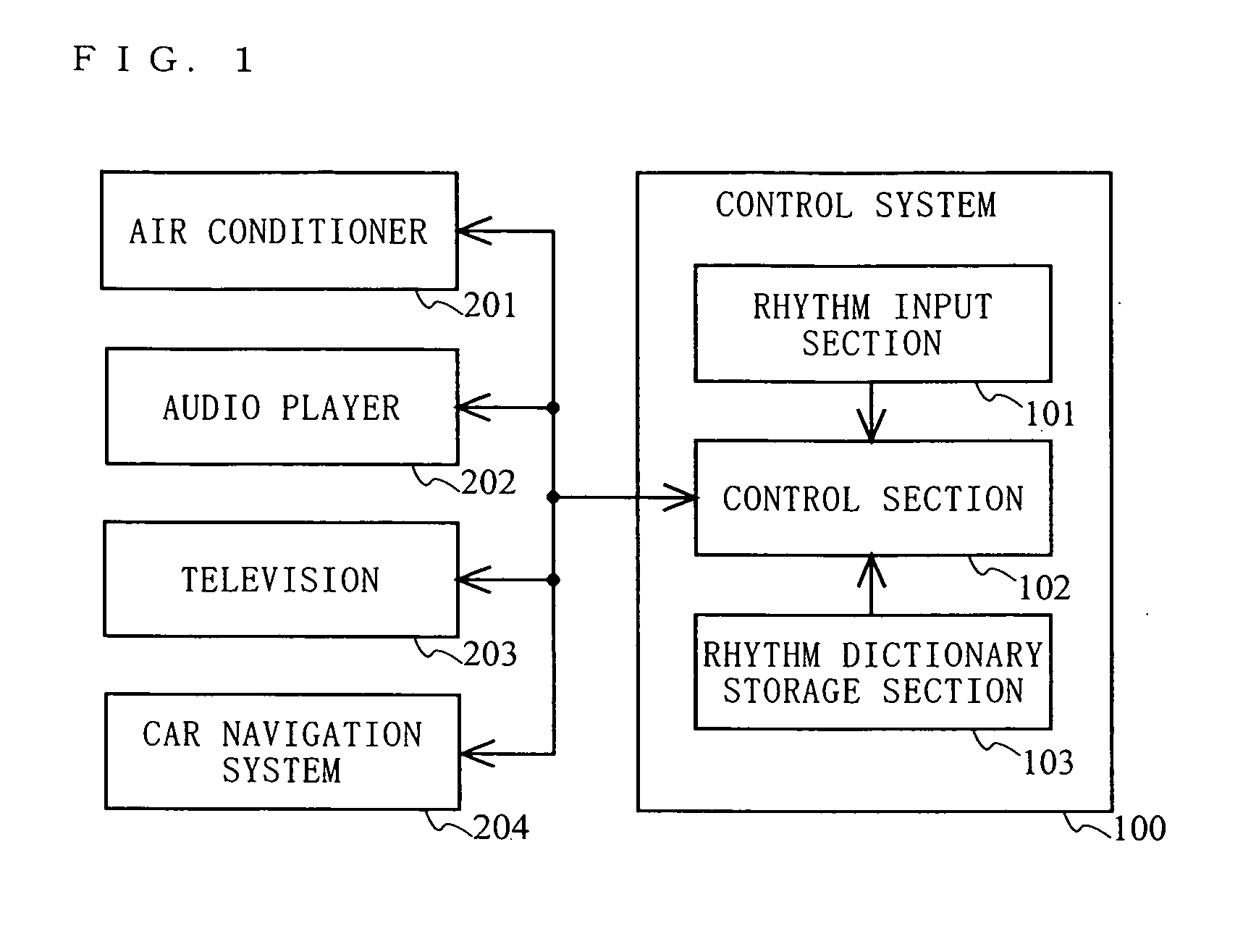
[0123]FIG. 1 is a diagram showing a structure of a control system 100 according to the first embodiment of the present invention and a whole structure of a system to which the control system 100 is applied. In this embodiment, for the sake of simplicity, the control system 100 is assumed to be a system for controlling in-vehicle apparatuses, such as an air conditioner, an audio player and the like.

[0124] In FIG. 1, the whole system comprises the control system 100, an air conditioner 201, an audio player 202, a television 203, and a car navigation system 204. The air conditioner 201, the audio player 202, the television 203 and the car navigation system 204 are apparatuses mounted in a vehicle (hereinafter referred to as in-vehicle apparatuses). In-vehicle apparatuses described herein are for illustrative purpose only. In-vehicle apparatuses other than those of FIG. 1 may be included in the system. Alternatively, only a portion of the in-vehicle apparatuses of FIG. 1 may be include...

second embodiment

[0162] A whole structure of a system according to a second embodiment of the present invention is similar to that of the first embodiment, and therefore, FIG. 1 is referenced in the second embodiment. Hereinafter, a difference between the first embodiment and the second embodiment will be mainly described.

[0163] In the second embodiment, the rhythm input section 101 is composed of an analog input device, such as a piezoelectric sensor or the like.

[0164]FIG. 10 is a diagram schematically showing a waveform of an input rhythm signal output from the rhythm input section 101 in the second embodiment. In the second embodiment, a strong beat level and a weak beat level are predetermined. Since the rhythm input section 101 is an analog input device, an amplitude level of an output signal thereof varies depending on tapping by the user as shown in FIG. 10. In the second embodiment, a time at which an amplitude level of the waveform which exceeds the strong or weak beat level and has a pea...

third embodiment

[0182] A whole structure of a system according to a third embodiment of the present invention is similar to that of the first embodiment, and therefore, FIG. 1 is referenced in the third embodiment. In the third embodiment, the rhythm input section 101 may be either a digital input device or an analog input device.

[0183] Hereinafter, an operation of a control section 102 of the third embodiment will be described. A main operation of the control section 102 when arhythm is input by the user is similar to that of the first embodiment, and therefore, FIG. 6 is referenced. The third embodiment is different from the first embodiment in the input rhythm pattern recognition process.

[0184]FIG. 14 is a flowchart showing a detailed operation of the control section 102 of the third embodiment in the input rhythm pattern recognition process. Hereinafter, the operation of the control section 102 in the input rhythm pattern recognition process will be described with reference to FIG. 14.

[0185]...


PUM


Abstract

A control system for reliably performing minimally required operations using a small number of input devices is provided. A rhythm input section (101) converts a rhythm pattern input by the user to an electrical signal, which is in turn output. A rhythm dictionary storage section (103) stores a rhythm dictionary table which associates the contents of a control of an apparatus with a registered rhythm pattern. The registered rhythm pattern is obtained by typifying a pronunciation pattern of a name indicating the contents of the control. A control section (102) analyzes the electrical signal from the rhythm input section (101) to recognize the input rhythm pattern input by the user, recognizes the contents of a corresponding control by referencing the rhythm dictionary storage section (103), and controls an operation of an in-vehicle apparatus.

Description

TECHNICAL FIELD [0001] The present invention relates to a system for controlling operations of various apparatuses. More particularly, the present invention relates to a system providing a user interface for employing a small number of operating devices to control operations of various apparatuses. BACKGROUND ART [0002] Recent various apparatuses, such as, particularly, AV apparatuses (e.g., television, video and audio apparatuses, etc.), in-vehicle apparatuses (e.g., car navigation and car audio apparatuses, etc.) and the like, have considerably many functions. Along with it, the number of operating devices, such as keys and joysticks, which are mounted on an apparatus body or a remote controller, is increased. The increased number of operating devices makes it difficult to operate the apparatus. [0003] Also, it is difficult to arrange input devices supporting tens or hundreds of functions in a limited space. [0004] To solve such problems, various systems have been proposed. For ex...

Claims


Application Information

Patent Timeline
IPC IPC(8): G10H1/40G06F3/00G06F3/01G06F3/023
CPCG06F3/023G06F3/011
Inventor YAMASHITA, ATSUSHISAKAMOTO, KIYOMIIISAKA, ATSUSHI
Owner PANASONIC CORP
Learn More