
Method and device for the position-dependent control of a mobile element in a motor vehicle

Inactive Publication Date: 2006-01-12
BROSE FAHRZEUGTEILE GMBH & CO KG +1
View PDF17 Cites 4 Cited by
  • Summary
  • Abstract
  • Description
  • Claims
  • Application Information

AI Technical Summary

Benefits of technology

[0009] Accordingly, the present invention is based on the task to provide a method according to the preamble of Claim 1 and a device that, despite of the described critical operating states of the electrical positioning device, provide for a safe and reliable operation of the positioning device.
[0014] The method according to the invention provides for a simple and inexpensive way to control the various operating modes of the positioning device in dependence of the above mentioned parameters, so that after or during the described critical operating states of the positioning device the safety requirements of the operation of the positioning device are at all times met. This can take place, for example, through the deactivation of the automatic operation of the positioning device or through adjusting the position of the mobile element in dependence of the determined error value.
[0016] Further, it is advantageous to form a correlated error value out of at least two of the determined error values by means of a mathematical correlation, and to control at least one operating mode of the positioning device in dependence of the correlated error value. In particular, an addition or a multiplication are possible as mathematical correlations. In this way, several linked error values can be formed out of the number of characteristic variables and / or specific values.
[0018] For the determination of relative error values the characteristic variables and / or specific values can preferably be compared with an assigned threshold value. It is thereby particularly advantageous if characteristic variables and / or specific values are transformed so that they can be compared with one or more uniform threshold values for the determination of the error values. In that way, the number of threshold values required for the method can be reduced.
[0020] As already mentioned previously, the various operating modes of the positioning device differ, for example, in that at least one of the following characteristics of the positioning device is changed: positioning speed of the mobile element, activity of a crush guard, activity of an automatic operation for the automatic movement of the mobile element in a first and / or second end position and adjustment of a determined position of the mobile element in an end position. Through the variety of possible operating modes and their differentiated control by means of the above-mentioned types an intelligent control of the positioning device is provided that makes safety requirements for different user profiles under complex constellations of the evaluated parameters (characteristic variables / specific values) possible.
[0026] The respectively determined value of the partial error is preferably implemented as a function of the assigned characteristic variable or the assigned specific value. In this way, a weighing of the influence of the different parameters on the error indicator is achieved in a simple manner.

Problems solved by technology

In these critical operating states, the current impulses for the determination of the positioning path are difficult to evaluate, or cannot be evaluated at all.
This leads necessarily to a deviation between the position of the mobile element determined using the current impulses and its real position.
This error leads, in particular when the “ripple-count” method is used for power windows of automobiles, to the following problem.
If the error in determining the position is, for example, in the range of a tenth of a millimeter, this legal requirement can no longer be reliably met.

Method used


Image

  • Method and device for the position-dependent control of a mobile element in a motor vehicle
  • Method and device for the position-dependent control of a mobile element in a motor vehicle
  • Method and device for the position-dependent control of a mobile element in a motor vehicle

Examples


first embodiment

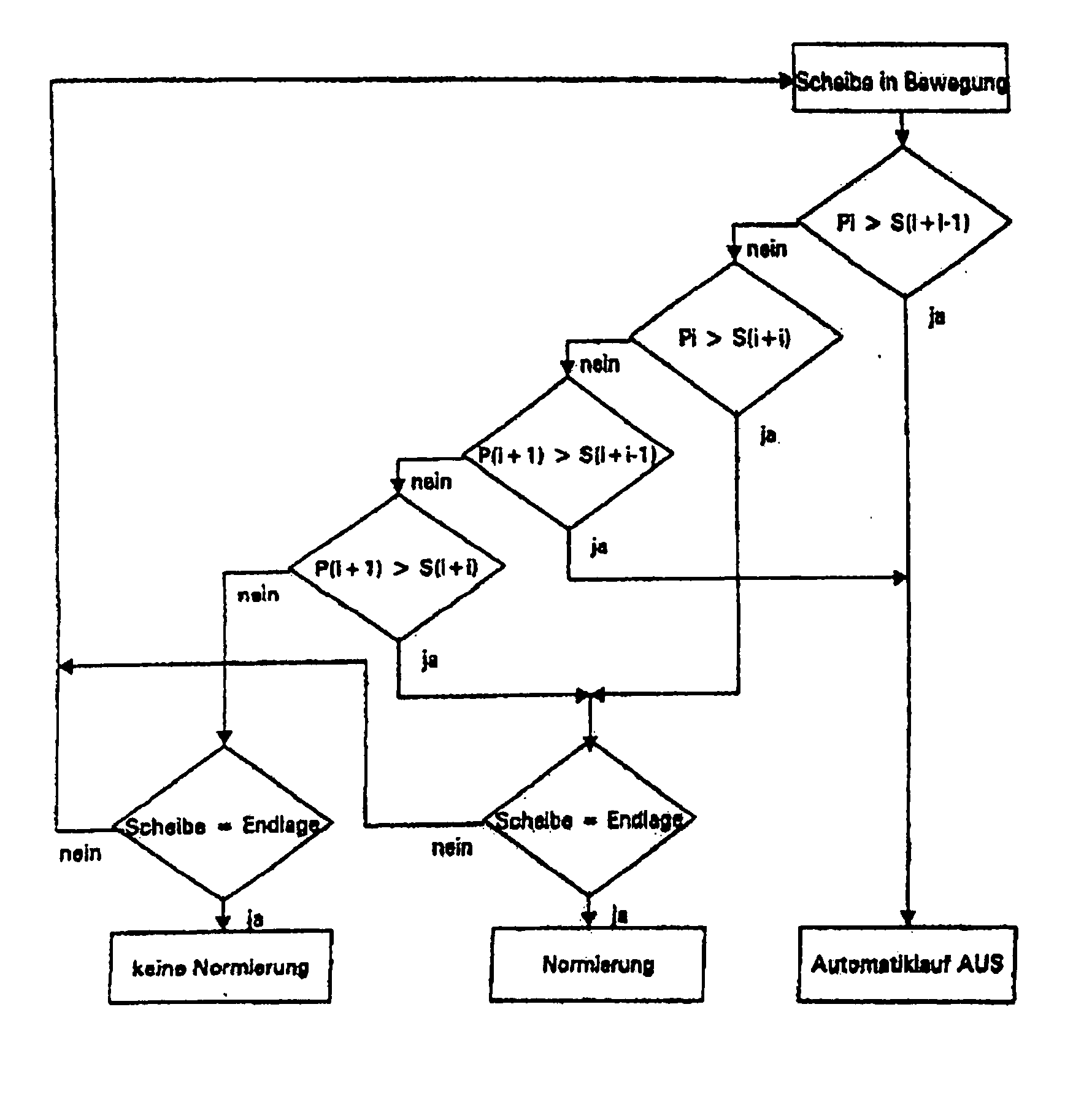
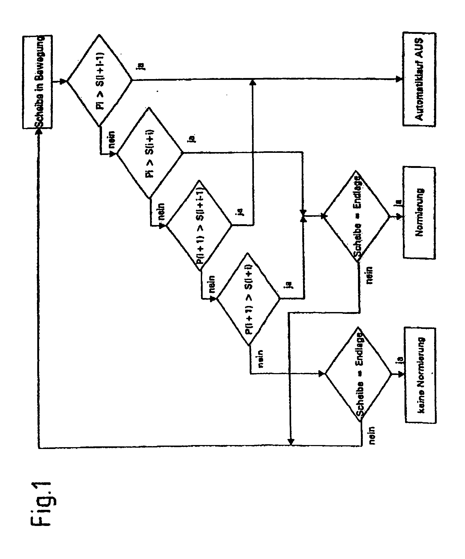
[0045]FIG. 1 shows the method according to the invention in form of a flow diagram. For illustrative purposes, a selected application of the method is for a positioning device for a power window of an automobile.

[0046] Initially, the positioning device is in its basic operating mode. The position of the window determined by the positioning device then matches within the range of the acceptable error with the actual position of the window, and upon reaching one of the end positions of the window it is not necessary to perform an adjustment of the window.

[0047] While the window is moving, the parameter Pi is first compared with a first decision threshold value Si+i−1. If this first decision threshold value Si+i−1 is exceeded, the automatic operation of the positioning device is deactivated. For example, this may be the case if variations of the vehicle's electric power occurred such that the absolute error of the window position, which is determined by the positioning device, is in t...

second embodiment

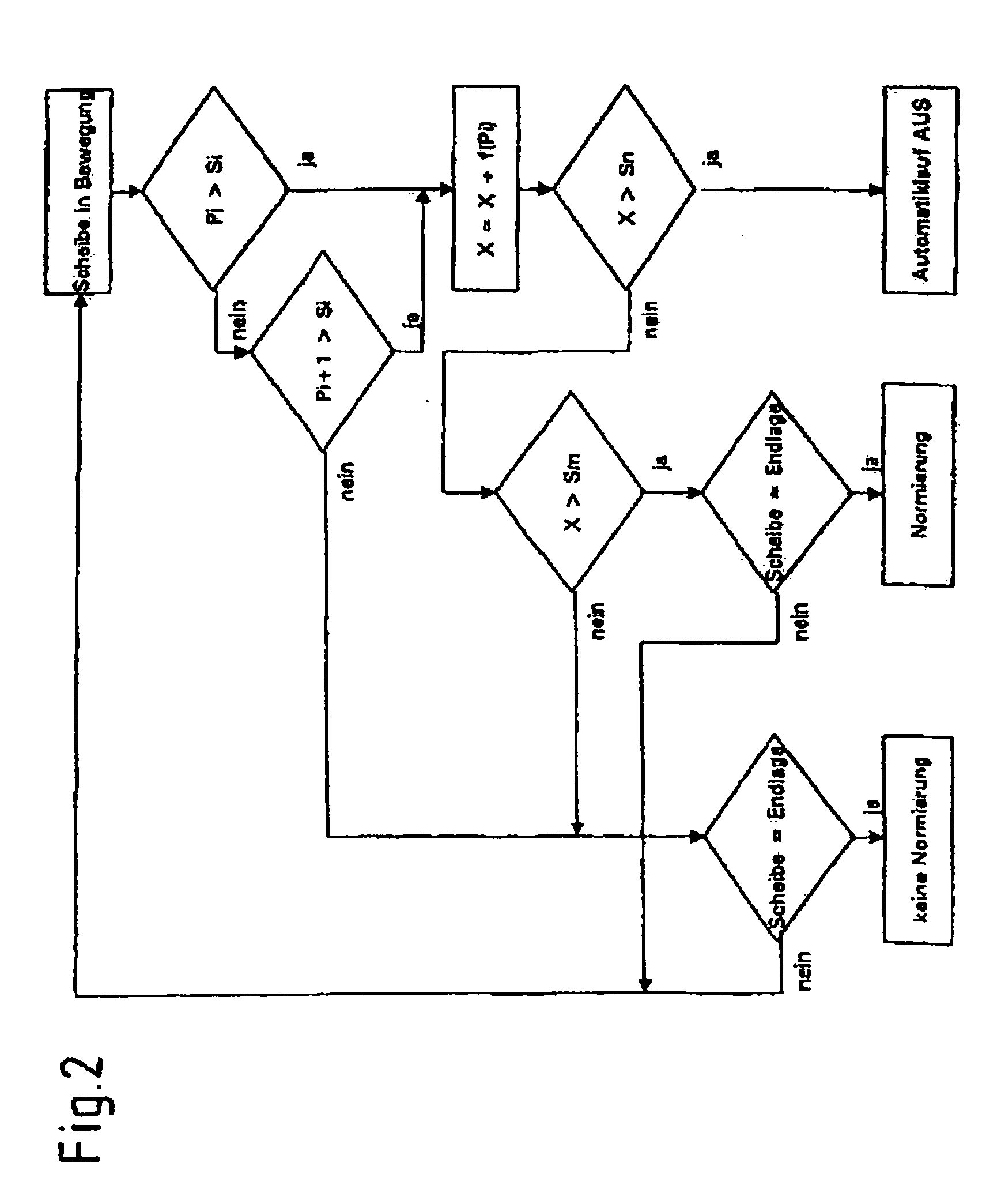
[0054]FIG. 2 shows the flow diagram of the method according to the invention. Initially, like in the previous embodiment, the positioning device is in the basic operating mode. While the window is moving the parameters Pi are compared with a threshold value Si. If this threshold value Si is exceeded, an error indicator X is increased by one partial error f(Pi).

[0055] If the threshold value Si is not exceeded, the comparison of the next parameter Pi+1 with the threshold value Si follows. If the threshold value is then exceeded the increase of the error indicator X by one partial error f(Pi+1) follows. Each partial error is preferably a function of the parameter Pi.

[0056] After each increase of the error indicator X, the error indicator X is subsequently compared a first decision threshold value Sn. If the decision threshold value Sn is exceeded, the operating mode of the positioning device is changed so that its automatic operation, in particular towards the closed end position, is ...


PUM


Abstract

The present invention concerns a method for the position-dependent control of a mobile element in a motor vehicle, wherein the element is movable in a drive movement by an electrically powered positioning device, wherein the positioning device has several different operational modes, and characteristics of a drive signal of the positing device, in particular a waviness of a drive current, are used for the determination of the position of the element. According to the invention, a characteristic variable, which influences the drive movement of the positioning device, and / or a specific value, which characterizes the positioning device, are evaluated for the determination of an error value of the determined position of the mobile element, and that the operating modes of the positioning device are controlled in dependence of the determined error value.

Description

CROSS REFERENCE TO RELATED APPLICATIONS [0001] The present application is a continuation of International Application PCT / DE03 / 04089, filed Dec. 5, 2003, and further claims priority to German patent application 10258476, filed Dec. 10, 2002, the both of which are herein incorporated by reference.BACKGROUND OF THE INVENTION [0002] The invention concerns a method for the position-dependent control of a mobile element in a motor vehicle, wherein the element is movable in a drive movement by an electrically powered positioning device, according to the preamble of Claim 1. [0003] Accordingly, the positioning device has several different operational modes, and characteristics of a drive signal of the positioning device, in particular a waviness of a drive current, are used for the determination of the position of the element. [0004] The different operational modes of the positioning device can in particular contain the activation and deactivation of the automatic operation of the mobile e...

Claims


Application Information

Patent Timeline
IPC IPC(8): B60G17/016B60N2/02E05F15/16
CPCB60N2/0252B60N2002/0268E05F15/689B60N2002/0272E05Y2900/55B60N2/0272B60N2/0268
Inventor SEEBERGER, JURGENABERT, CARSTEN
Owner BROSE FAHRZEUGTEILE GMBH & CO KG
Learn More