
Wireless audio transmission/reception system and using method therefor

a technology of audio transmission and reception system, applied in the field of wireless audio transmission/reception system, can solve the problems of difficult for users to select difficulty in a user's selection of a desired frequency channel among the available frequency channels, and inability to achieve the desired frequency, etc., to achieve convenient optimal frequency and obtain optimal audio tx/rx frequency

Inactive Publication Date: 2006-01-12
LG ELECTRONICS INC
View PDF5 Cites 8 Cited by
  • Summary
  • Abstract
  • Description
  • Claims
  • Application Information

AI Technical Summary

Benefits of technology

[0011] An object of the present invention is to provide a wireless audio transmission / reception system and a using method therefor, which can conveniently obtain an optimal audio TX / RX frequency.
[0012] Another object of the present invention is to provide a wireless audio transmission / reception system and a using method therefor, which can conveniently set an optimal frequency.
[0013] A further another object of the present invention is to provide a wireless audio transmission / reception system and a using method therefor, which can conveniently set an optimal audio TX / RX frequency.
[0021] Accordingly, an optimal TX / RX frequency can conveniently obtained and thus user convenience is enhanced.

Problems solved by technology

Accordingly, there is a high possibility that a frequency signal used by the FM transmitter might interfere with a frequency signal used by the general radio broadcast.
However, it is very difficult for a user to select a desired frequency channel among the available frequency channels.
However, radio frequency signals include not only a signal of a predetermined frequency used but also a signal in a different frequency band that may interfere with the original frequency.
Accordingly, such a method is not desirable.
Therefore, interference between radio signals, signals reflected by the building, and electromagnetic wave signals due to other neighboring electronic devices greatly affect the apparatus.
Therefore, it is problematic to have the audio replay system disposed inside the building transmit and receive audio signals over a predetermined radio frequency.

Method used


Image

  • Wireless audio transmission/reception system and using method therefor
  • Wireless audio transmission/reception system and using method therefor
  • Wireless audio transmission/reception system and using method therefor

Examples


first embodiment

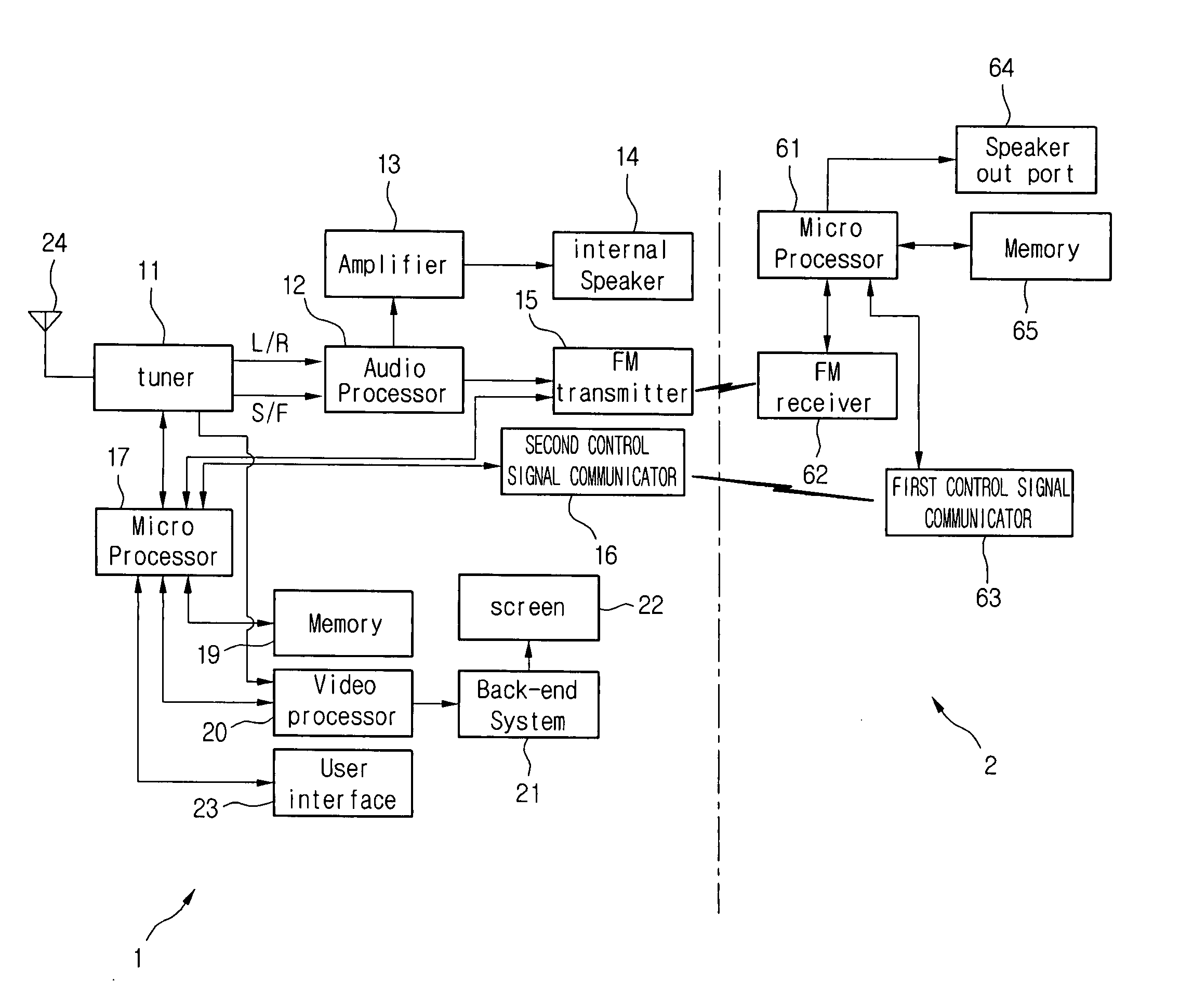
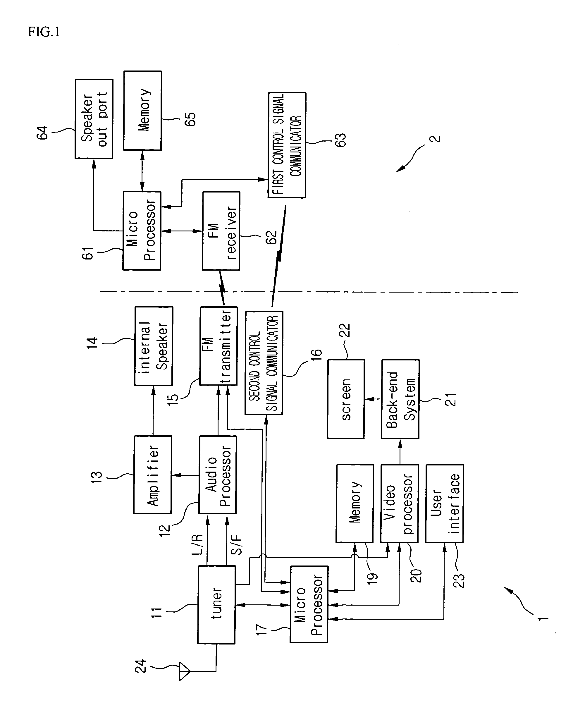
[0030]FIG. 1 is a block diagram of a wireless audio transmission / reception system according to a first embodiment of the present invention.

[0031] Referring to FIG. 1, a wireless audio transmission / reception system includes an audio replay system 1 and an external audio system 2. The audio replay system 1 is an audio output system that can replay audio. For example, the audio replay system 1 may a MP3 player, a display device, a mobile terminal, a DVD player, a VCR, a Set-top box, a personal computer, a game device, a camcorder, or the like. The external audio system 2 is spaced apart from the audio replay system 1. The external audio system 2 is a speaker-equipped system such as a car audio, an audio system, a speaker, and a remote controller.

[0032] A display device and a remote controller are exemplarily illustrated as the audio replay system 1 and the external audio system 2 to describe the present invention.

[0033] Hereinafter, the wireless audio transmission / reception system o...

second embodiment

[0062]FIG. 4 is a block diagram of a wireless audio transmission / reception system according to a second embodiment of the present invention.

[0063] The second embodiment of the present invention is the same as the first embodiment except that the process of setting the using channel is set by the audio reproducing system 1, not by the external audio system 2. Therefore, descriptions of parts not mentioned particularly in the second embodiment are the same as those in the first embodiment. Only different part will be described below.

[0064]FIG. 4 is a block diagram of a wireless audio transmission / reception system according to the second embodiment of the present invention.

[0065] Referring to FIG. 4, the audio reproducing system 1 further includes an FM detector 18 for exploring a radio FM channel and an FM antenna 25 for transmitting radio signals to the FM detector 18.

[0066] With such a structure, after information of the FM channel explored by the FM antenna 25 and the FM detect...

third embodiment

[0069] The third embodiment is identical to the second embodiment with the exception that transmission / reception of a control signal between the audio replay system and the external audio system is differently performed in the embodiments.

[0070] In the first and second embodiments, one of the audio replay system and the external audio system receives a radio broadcast signal, detects an occupied channel that is currently used, selects a possible channel using the occupied channel, set the possible channel to a using channel, and transmits information about the using channel to the other system.

[0071] However, the first embodiment is problematic in that the external audio system with a low capacity should perform a complex operation. Also, the second embodiment is problematic in that the audio replay system should additional include an FM detector 18 and an FM antenna 25.

[0072] To solve these problems, it is more preferable to utilize the high operation capability of the controlle...


PUM


Abstract

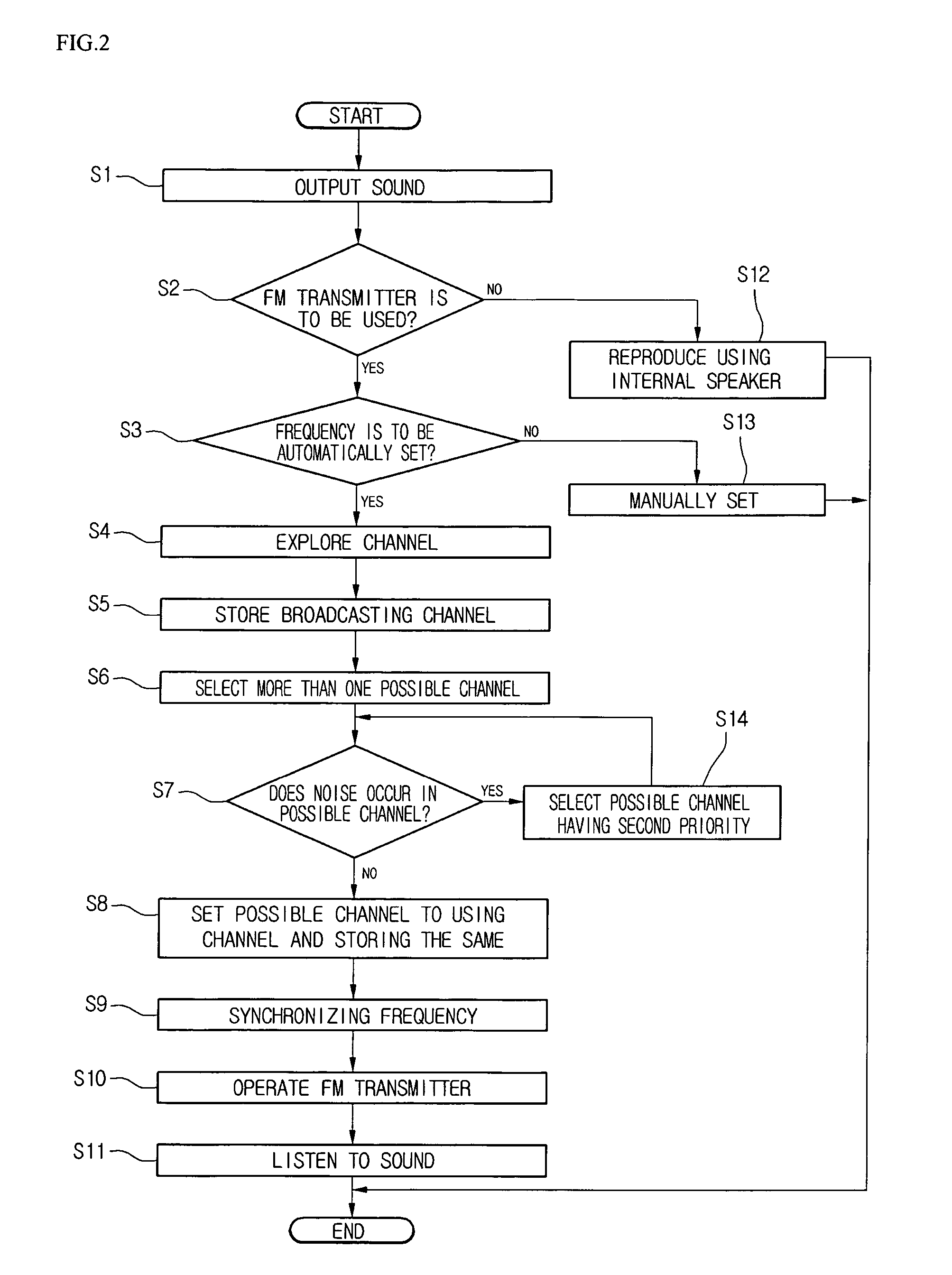
A wireless audio transmission / reception system is provided. The transmission / reception system includes an FM detector for detecting an occupied channel among radio FM channels, a microprocessor for selecting a using channel that is greatly different in frequency from the detected occupied channel and thus does not interfere therewith, an FM transmitter built in an audio replay system to transmit / receive an audio signal over the using channel, and an external audio system for receiving and outputting the audio signal from the FM transmitter.

Description

BACKGROUND OF THE INVENTION [0001] 1. Field of the Invention [0002] The present invention relates to a wireless audio transmission / reception system and a method for a radio frequency (RF) setting method therein, and particularly, to a wireless audio transmission / reception system and a using method therefor that allow a user to listen to an audio from an audio replay system by wireless. More particularly, the present invention relates to a wireless audio transmission / reception system and a using method therefor that can enhance user convenience and satisfaction by setting exact transmission / reception frequencies when audio signals reproduced by an audio replay system are transferred to an external audio system by an FM transmitter. [0003] 2. Description of the Related Art [0004] When an audio replay system (e.g., an MP3 player) and an external audio system (e.g., a car audio system) are separated from each other, an FM transmitter transmits audio signals reproduced by the audio repla...

Claims


Application Information

Patent Timeline
IPC IPC(8): H04B7/00
CPCH03J1/0008H04H20/02H04H20/61H04H40/18
Inventor HUR, MIN YOUNGSHIN, HYUN YUN
Owner LG ELECTRONICS INC
Learn More