
Image taking apparatus

a technology of image taking and apparatus, applied in the direction of printers, cameras, instruments, etc., to achieve the effect of maintaining the continuity of operation

Inactive Publication Date: 2006-01-12
KONICA MINOLTA PHOTO IMAGING
View PDF2 Cites 26 Cited by
  • Summary
  • Abstract
  • Description
  • Claims
  • Application Information

AI Technical Summary

Benefits of technology

[0007] A main object of the present invention is to provide an image taking apparatus capable of maintaining the continuity of the operation associated with the movement of the position of the focus adjustment area.
[0008] Another object of the present invention is to provide an image taking apparatus capable of reducing the trouble of performing the operation associated with the movement of the position of the focus adjustment area.

Problems solved by technology

However, in the conventional digital camera, since the position of the focus adjustment area is fixed immediately after the shift to the focus adjustment mode in which the position of the focus adjustment area is movable, there are cases where the user is forced to largely move the position of the focus adjustment area after the shift to the focus adjustment mode by a manual operation.

Method used


Image

  • Image taking apparatus
  • Image taking apparatus
  • Image taking apparatus

Examples


Embodiment Construction

[0028] Hereinafter, an embodiment of the image forming apparatus according to the present invention will be described with reference to the attached drawings.

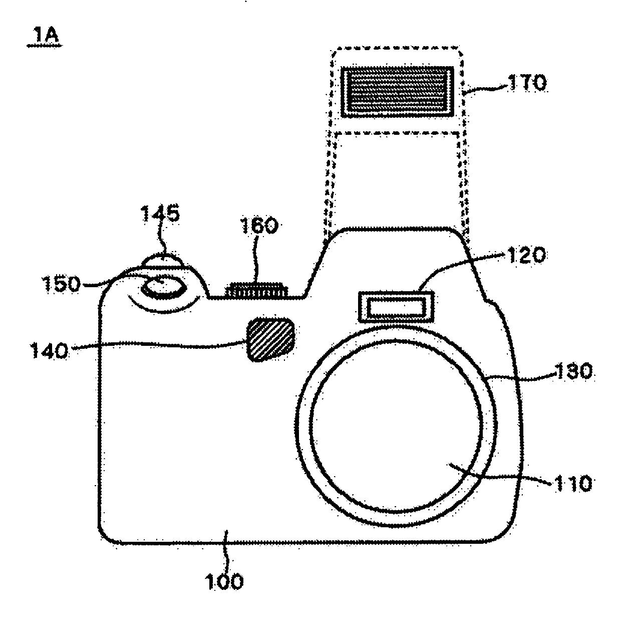
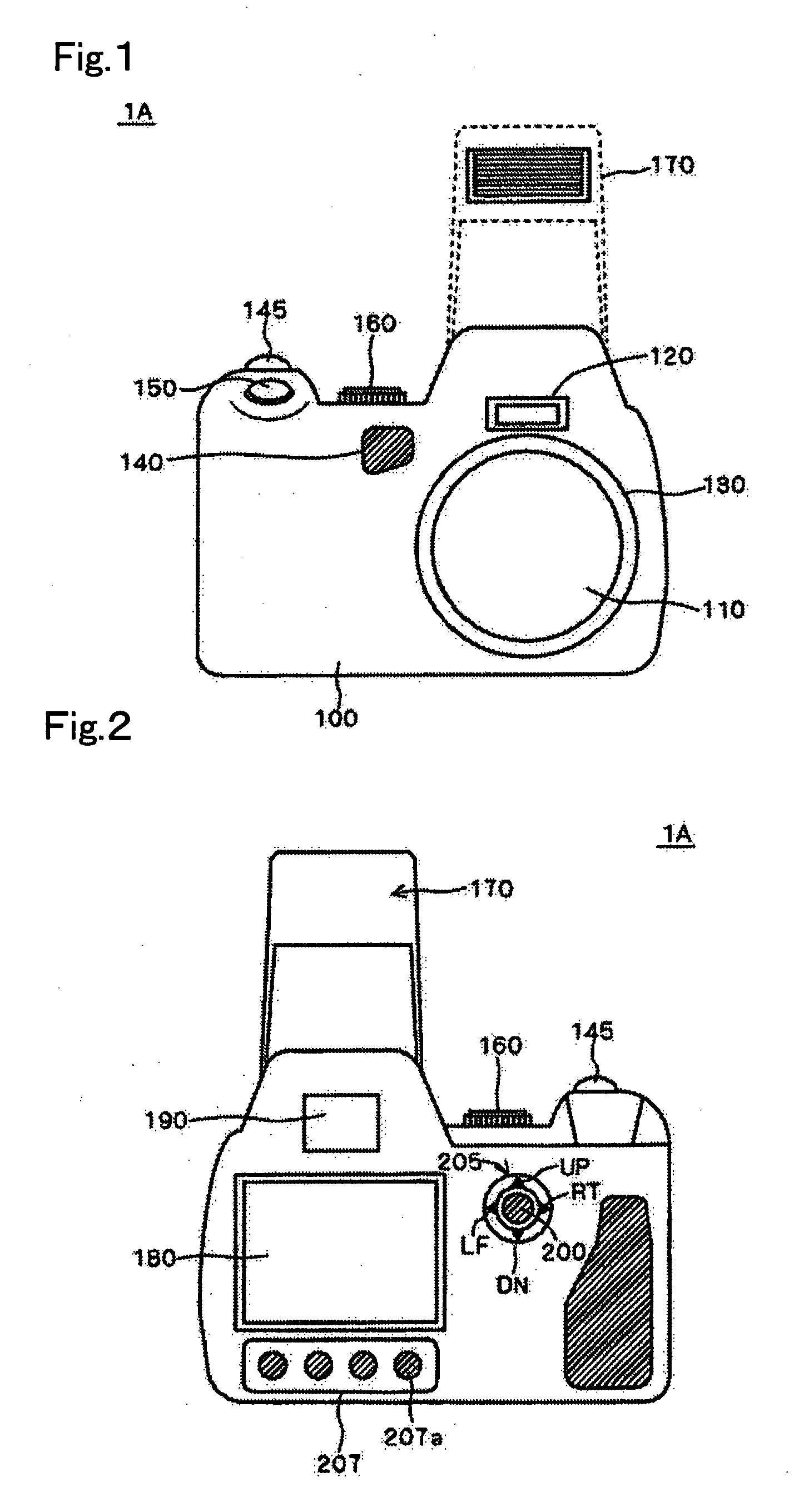
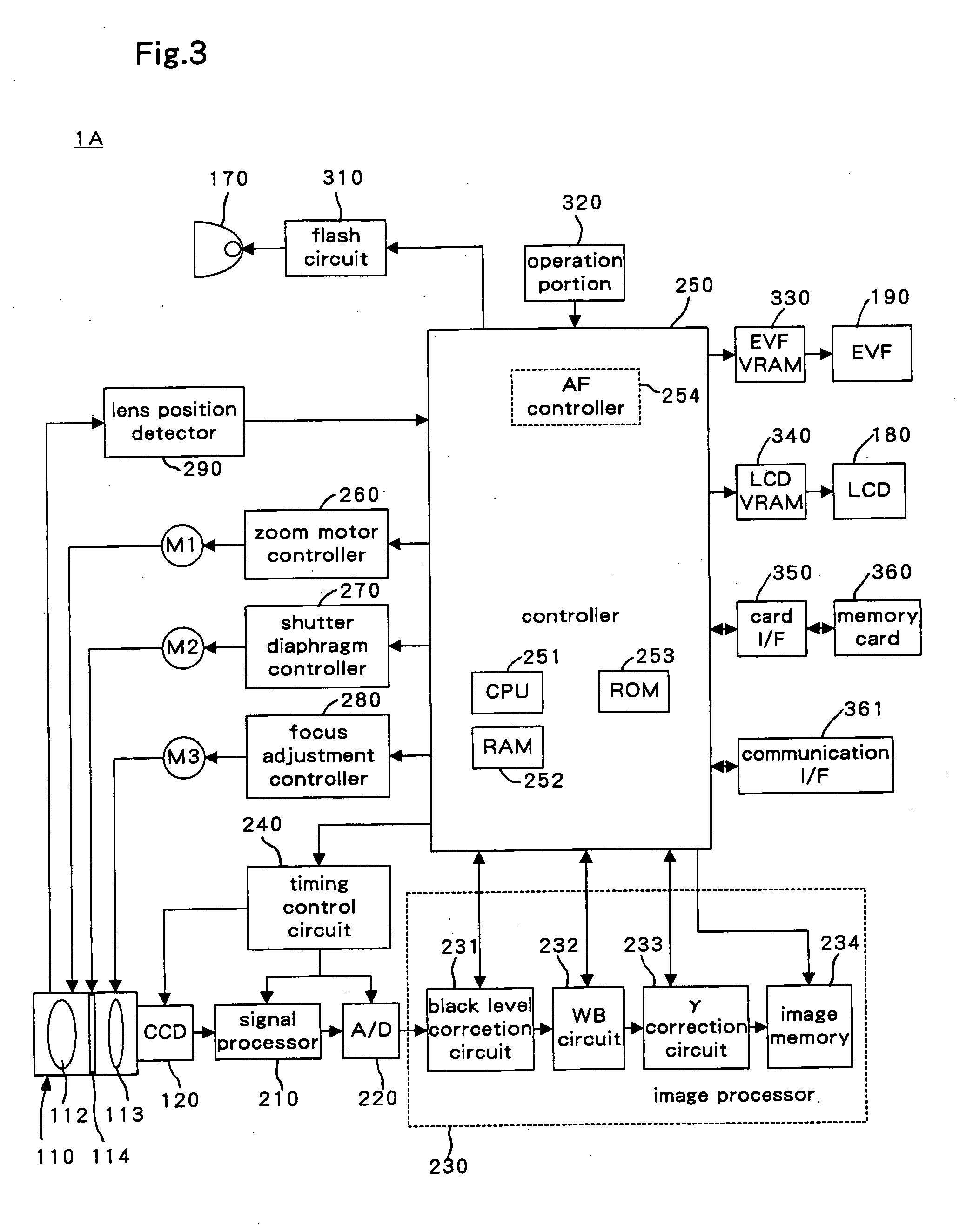
[0029] A digital camera 1A according to the embodiment of the present invention has an AF (automatic focusing) function, and is provided with a plurality of AF modes (focus adjustment modes) associated with AF. These plurality of AF modes include a multi-segment AF mode and an FFP (flex focus point) AF mode in which the position of the AF area (focus adjustment area) within the captured image is movable. In the digital camera 1A, when the AF mode is switched to the multi-segment AF mode or to the FFP AF mode, the position of the AF area immediately after the switching is determined based on the position of the representative point of the AF area immediately before the switching. The structure and operation of the digital camera 1A will be described below. The multi-segment AF mode referred to here is an AF mode in which the AF...


PUM


Abstract

In an image taking apparatus according to the present invention, focus adjustment is performed based on image information in a focus adjustment area within a captured image in response to a movement instruction from a user as well as a focus adjustment mode switching instruction from the user. When detecting an instruction to switch to a position non-fixed focus adjustment mode, an initial position of the focus adjustment area in the position non-fixed focus adjustment mode immediately after mode switching is determined based on a position of a representative point of the focus adjustment area immediately before the mode switching.

Description

CROSS-REFERENCE TO RELATED APPLICATON [0001] This application is based on Japanese Patent Application No. 2004-199512 filed in Japan on Jul. 6, 2004, the entire content of which is hereby incorporated by reference. BACKGROUND OF THE INVENTION [0002] 1. Field of the Invention [0003] The present invention relates to an image taking apparatus having an automatic focusing function. [0004] 2. Description of the Related Art [0005] A digital camera has conventionally been known that uses, for focus adjustment, a focus adjustment area fixed in a central part of the captured image. Moreover, a digital camera has been used that is provided with a plurality of focus adjustment modes including a focus adjustment mode in which the position of the focus adjustment area is movable, in order to enable precise focusing on a specific subject. [0006] However, in the conventional digital camera, since the position of the focus adjustment area is fixed immediately after the shift to the focus adjustment...

Claims


Application Information

Patent Timeline
IPC IPC(8): G03B13/34
CPCG02B7/34G02B7/36H04N5/23293H04N5/23212G03B13/34H04N23/675H04N23/673H04N23/635
Inventor YAMAGUCHI, TAKEHISAFUJII, SHINICHIYASUDA, TAKASHI
Owner KONICA MINOLTA PHOTO IMAGING
Learn More