
Low cost emergency disk drive head retract architecture

a disk drive and low cost technology, applied in the direction of the support of the head, instruments, data recording, etc., can solve the problems of power coming from the need, damage to the disk drive and the read/write head,

Active Publication Date: 2006-01-12
AVAGO TECH INT SALES PTE LTD
View PDF6 Cites 8 Cited by
  • Summary
  • Abstract
  • Description
  • Claims
  • Application Information

AI Technical Summary

Benefits of technology

The present invention is a system for ensuring the voice coil motor in a disk drive is powered during a power loss. It uses a spindle motor with internal resistance and inductance to create a back electromotive force (BEMF) which is then transferred to a capacitor. The capacitor then powers the voice coil motor through a power switch circuit. The system alternates between a conducting state and a non-conducting state at a set frequency, ensuring power is always provided to the voice coil motor. This results in a more reliable and efficient system for ensuring power is always available to the voice coil motor.

Problems solved by technology

If the head is not moved to the parking zone prior to power down, the head will land on the disk after the disk stops spinning, potentially damaging the disk and the read / write head.
The problem is where does the power come from necessary to move the read / write head to the landing zone.

Method used


Image

  • Low cost emergency disk drive head retract architecture
  • Low cost emergency disk drive head retract architecture
  • Low cost emergency disk drive head retract architecture

Examples


Embodiment Construction

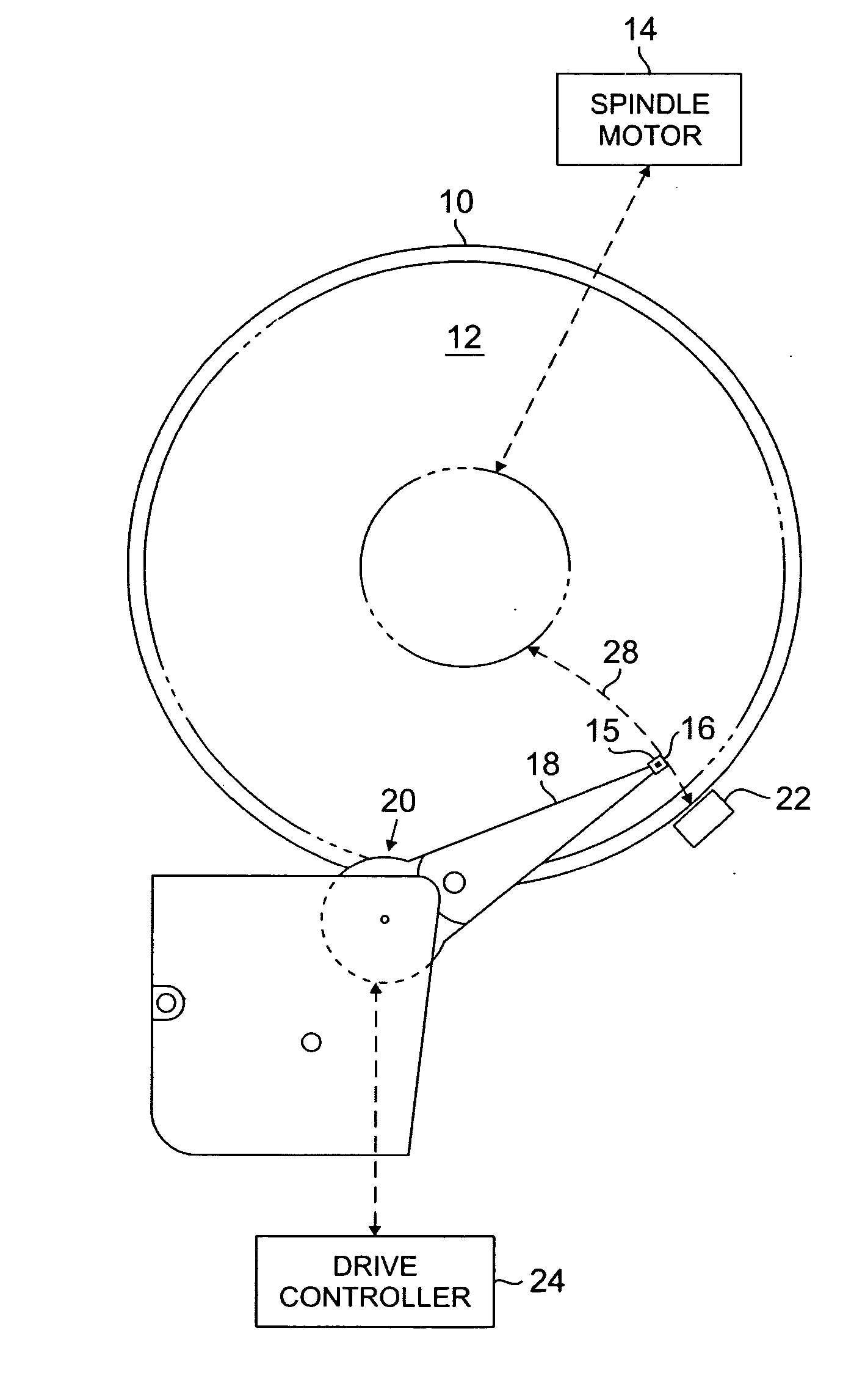
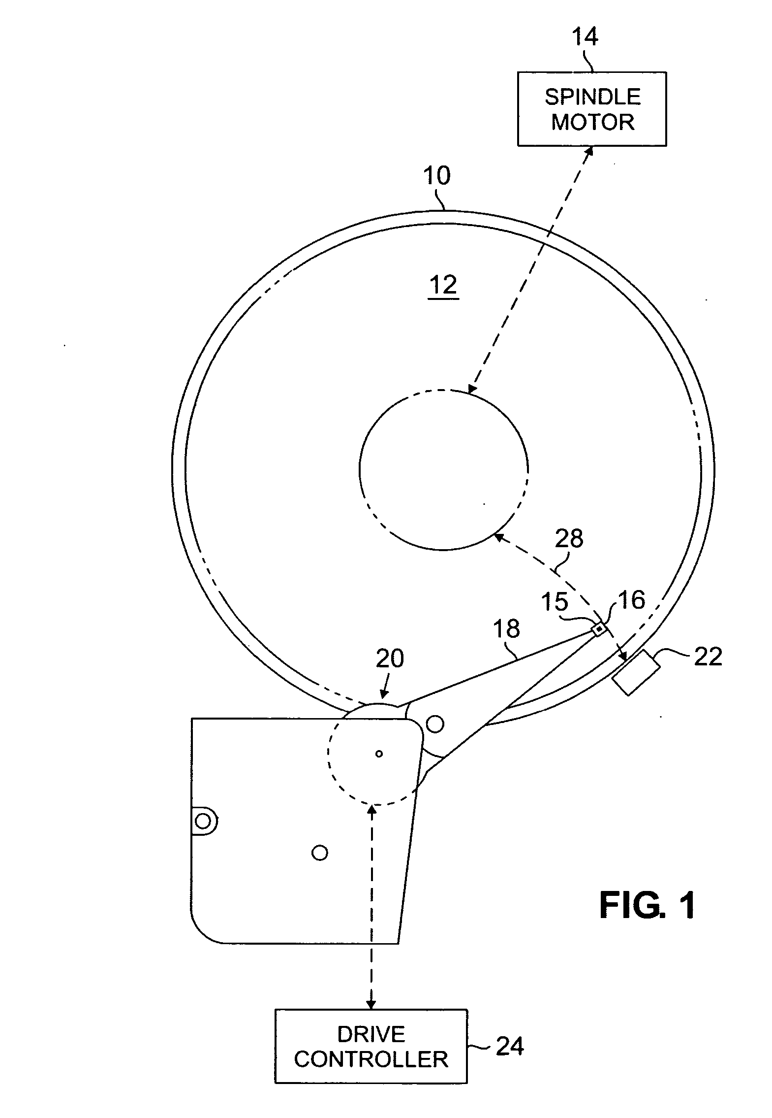
[0014]FIG. 1 is an illustration of typical disk drive system 10. Disk drive system 10 includes disk 12, spindle motor 14, slider 15 carrying read / write head 16, actuator arm 18, voice coil motor (“VCM”) 20, safe landing zone 22 and VCM control 24.

[0015] In normal operation, a drive current is provided to VCM 20 to actuate actuator arm 18. When actuated by VCM 20, actuator arm 18 can be moved from an inner diameter to an outer diameter of disk 12 along arc 28 until the read / write head 16 is positioned above a desired data track on the disk. Disk 12 includes a plurality of concentric tracks on which data and position information is recorded. Disk 12 is mounted on spindle motor 14, which causes disk 12 to spin. Read / write head 16 suspended from actuator arm 18 flies above the surface of disk 12 as it spins. Read / write head 16 is operable to read the data and position information from tracks of disk 12 and generate an input signal representative of the data and position information.

[0...


PUM

PropertyMeasurementUnit
voltageaaaaaaaaaa
poweraaaaaaaaaa
internal inductanceaaaaaaaaaa

Abstract

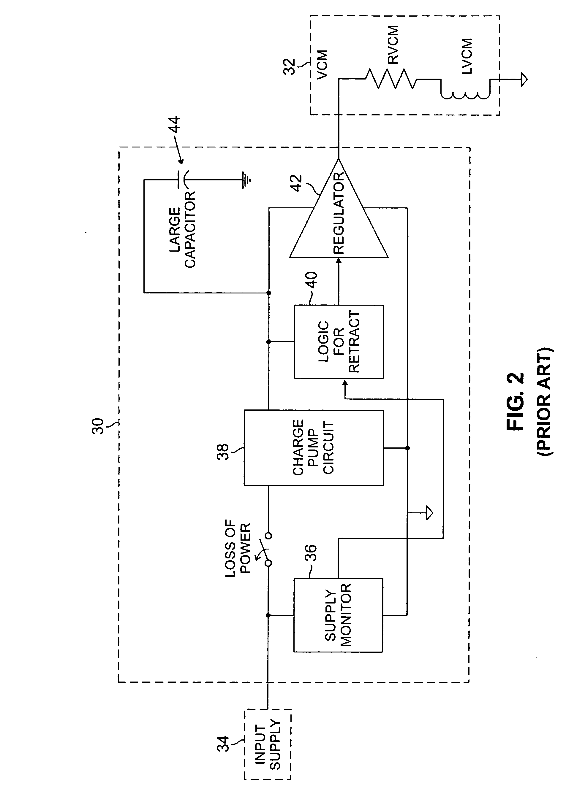
A disk drive emergency retract architecture for providing power to a voice coil motor (VCM) to retract a transducing head from a surface of a recordable medium during loss of power from an external power supply. The disk drive emergency retract architecture comprises a spindle motor, having an internal inductance and an internal resistance, for spinning the recordable medium. The spinning recordable medium creates a back electromotive force (BEMF) in the spindle motor. A boost circuit transfers the back electromotive force located in the spindle motor to a capacitor which stores and supplies power to the VCM. The capacitor is connected to a power switch circuit, which supplies power from the capacitor to the VCM when the power switch circuit is in a conducting state and prevents power from being supplied to by the capacitor to the VCM when the power switch circuit is in a non-conducting state. A retract circuit supplies a signal to the power switch circuit, dictating whether the power switch circuit is in the conducting state or the non-conducting state. The retract circuit operates to alternate the power switch circuit between the conducting state and the non-conducting state at a set frequency, resulting in power being provided from the capacitor to the VCM at this frequency.

Description

CROSS REFERENCE TO RELATED APPLICATION(S) [0001] This application claims the benefit of U.S. Provisional Application No. 60 / 590,207 filed Jul. 22, 2004 for “Low Cost Emergency Disk Drive Head Retract Architecture” by J. Brenden and J. Dahlberg. INCORPORATION BY REFERENCE [0002] The aforementioned U.S. Provisional Application No. 60 / 590,207 is hereby incorporated by reference in its entirety.BACKGROUND OF THE INVENTION [0003] The present invention relates to disk drives and storage devices. In particular, the present invention relates to utilizing back electromotive force (BEMF) energy from the spinning spindle motor to retract the head to a safe landing zone during emergency loss of power. [0004] Generally, a magnetic hard disk drive (HDD) includes a magnetic read / write head and several magnetic disks, each disk having concentric data tracks for storing data. The disks are mounted on a spindle motor, which causes the disks to spin. The read / write head is typically mounted on a slide...

Claims


Application Information

Patent Timeline
Patent Type & Authority Applications(United States)
IPC IPC(8): G11B21/02
CPCG11B21/12G11B5/54G11B21/02G11B21/08G11B21/26
Inventor BRENDEN, JASON P.DAHLBERG, JAMES A.
Owner AVAGO TECH INT SALES PTE LTD
Learn More