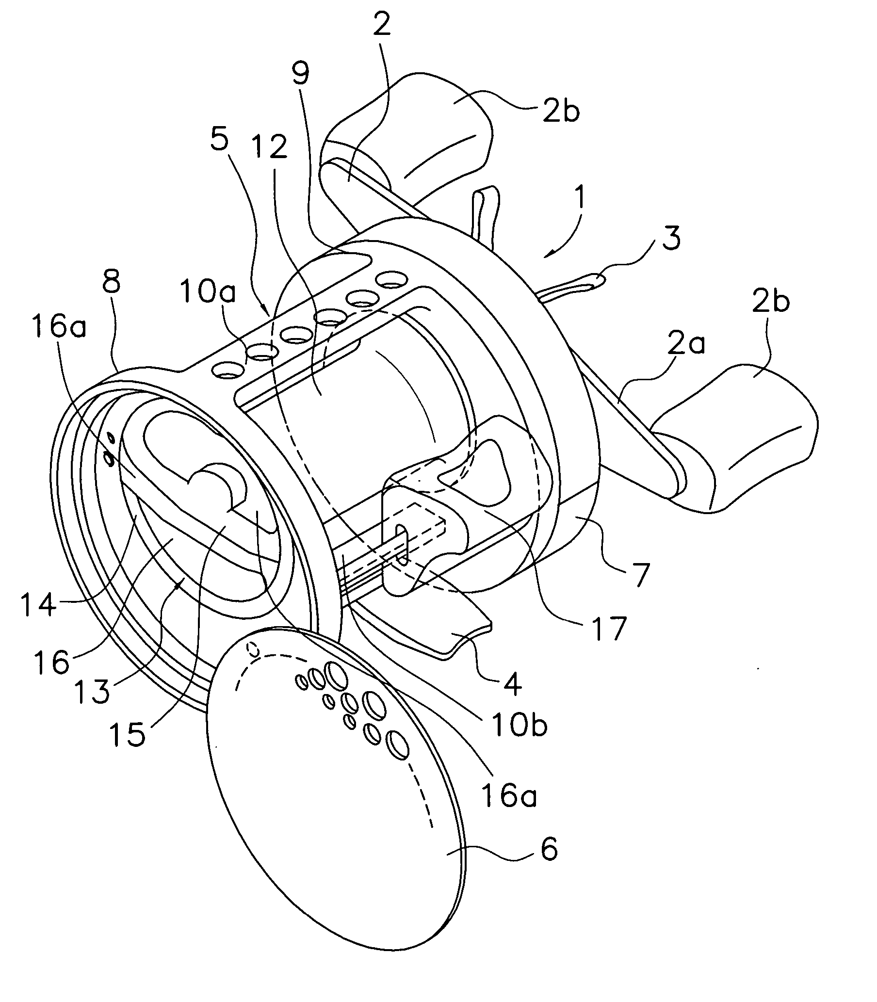
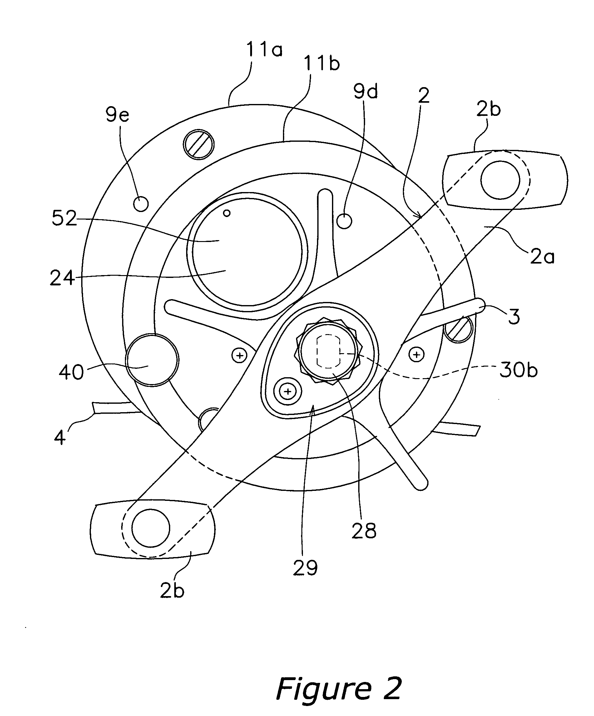
Spool assembly for a dual bearing reel
- Summary
- Abstract
- Description
- Claims
- Application Information
AI Technical Summary
Benefits of technology
Problems solved by technology
Method used
Image

Examples
second embodiment
[0115] Referring now to FIG. 16, a spool assembly in accordance with a second embodiment will now be explained. In view of the similarity between the first and second embodiments, the parts of the second embodiment that are identical to the parts of the first embodiment will be given the same reference numerals as the parts of the first embodiment. Moreover, the descriptions of the parts of the second embodiment that are identical to the parts of the first embodiment may be omitted for the sake of brevity.
[0116] In the first embodiment, the first fishing line entry prevention portion 12f and the second fishing line entry prevention portion 12g are arranged so that the side surfaces 121 on the bobbin 12a side are positioned further on the bobbin 12a side than the tip surfaces of the first annular portion 14a and the second annular portion 14b. The spool assembly of the second embodiment is essentially the same as in the first embodiment except that side surfaces 1121 on a bobbin sid...
third embodiment
[0118] Referring now to FIG. 17, a spool assembly in accordance with a third embodiment will now be explained. In view of the similarity between the first and third embodiments, the parts of the third embodiment that are identical to the parts of the first embodiment will be given the same reference numerals as the parts of the first embodiment. Moreover, the descriptions of the parts of the third embodiment that are identical to the parts of the first embodiment may be omitted for the sake of brevity.
[0119] The spool assembly of the third embodiment is essentially the same as in the first embodiment except that a lateral surface on an axially outward side of a first fishing line entry prevention portion (not shown) is positioned more axially inward than the first tip portion of the first annular portion 14a. Likewise, a lateral surface on an axially outward side of a second fishing line entry prevention portion 212g is positioned more axially inward than the second tip portion of ...
PUM
 Abstract
Description
Claims
Application Information
 - R&D
- Intellectual Property
- Life Sciences
- Materials
- Tech Scout
- Unparalleled Data Quality
- Higher Quality Content
- 60% Fewer Hallucinations
Browse by: Latest US Patents, China's latest patents, Technical Efficacy Thesaurus, Application Domain, Technology Topic, Popular Technical Reports.
© 2025 PatSnap. All rights reserved.Legal|Privacy policy|Modern Slavery Act Transparency Statement|Sitemap|About US| Contact US: help@patsnap.com