
Energy recovery unit

Active Publication Date: 2006-01-12
SPINNAKER INDS
View PDF12 Cites 3 Cited by
  • Summary
  • Abstract
  • Description
  • Claims
  • Application Information

AI Technical Summary

Benefits of technology

[0004] To minimize the energy consumption, it is known to recover energy from the expelled air and utilize it to precondition the makeup air. Such units may be as simple as counter-flow heat exchangers so that the outgoing air flows in a parallel path to the incoming air and energy is exchanged between the two. Alternatively, more sophisticated arrangements may be utilized in which the expelled air is forced through a rotary energy recovery unit. The energy recovery unit has a large rotating disc that traverses a pair of ducts, one for expelled air and one for makeup air. The wheel absorbs heat and / or moisture from the expelled air and transfers it to the duct carrying the makeup air. The ducts are maintained separate from one another to minimize cross bleeding of the air whilst the heat transfer efficiency is enhanced due to the large cross-sectional area presented by the disc that the air must pass through.
[0005] Such arrangements have improved the energy consumption significantly but do not readily lend themselves to compact installations within existing systems. Typically, the wheels are oriented on a horizontal axis that increases the overall height of the unit and requires it to be placed in a separate stand alone unit. This not only increases the expense of such a unit but also effects the aesthetics of the building upon which it is installed. Moreover, the ducting of air within the energy recovery unit results in the inlet and outlets being spaced apart a significant distance that further increases the size of the unit and the overall installation.

Problems solved by technology

However, the air rejected from the building has been conditioned so it represents a significant energy loss if it is simply expelled.
Such arrangements have improved the energy consumption significantly but do not readily lend themselves to compact installations within existing systems.
This not only increases the expense of such a unit but also effects the aesthetics of the building upon which it is installed.
Moreover, the ducting of air within the energy recovery unit results in the inlet and outlets being spaced apart a significant distance that further increases the size of the unit and the overall installation.

Method used


Image

  • Energy recovery unit
  • Energy recovery unit
  • Energy recovery unit

Examples


Embodiment Construction

[0008] An embodiment of the invention will now be described by way of example only with reference to the accompanying drawings in which:

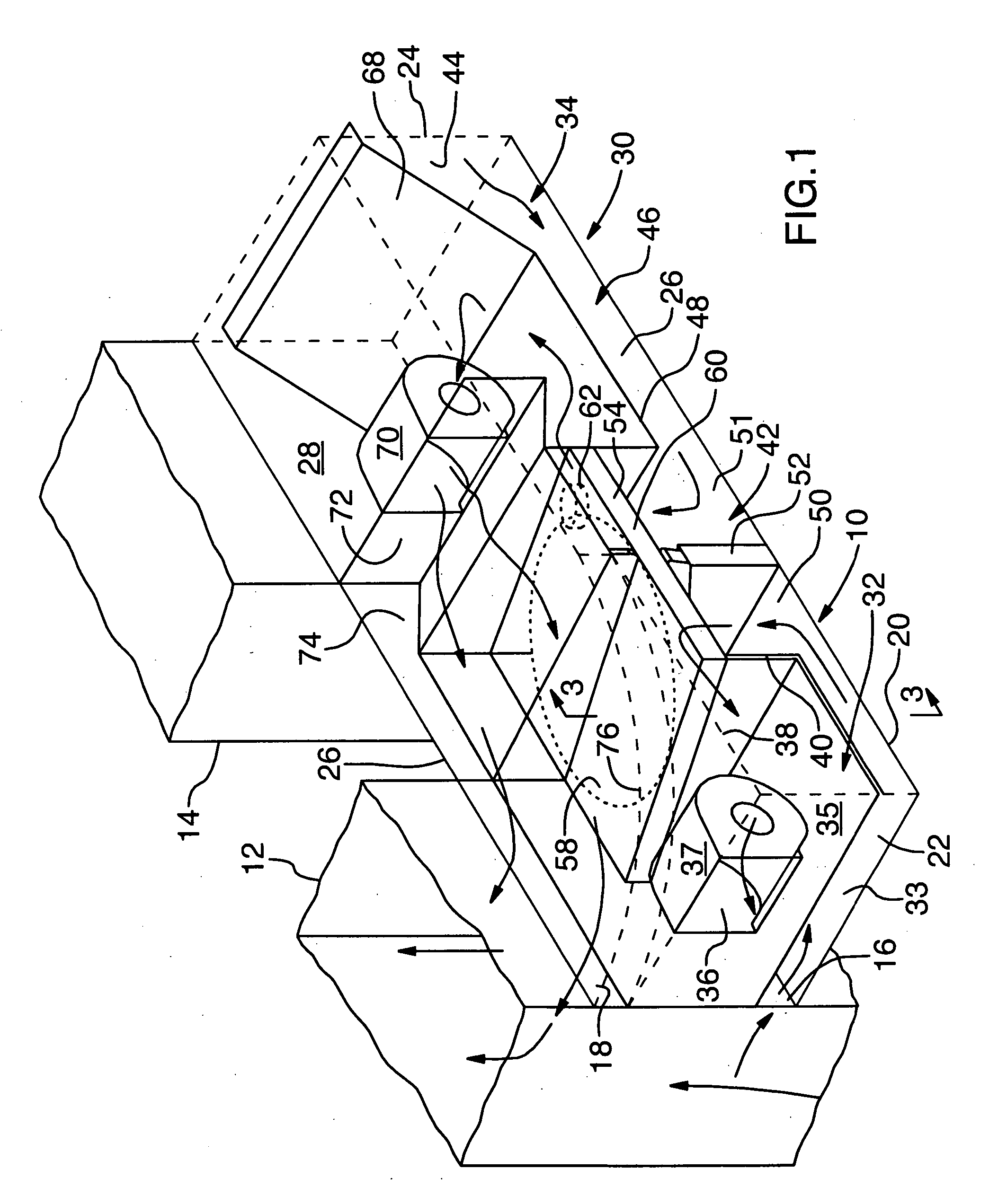
[0009]FIG. 1 is a perspective view of an energy recovery unit.

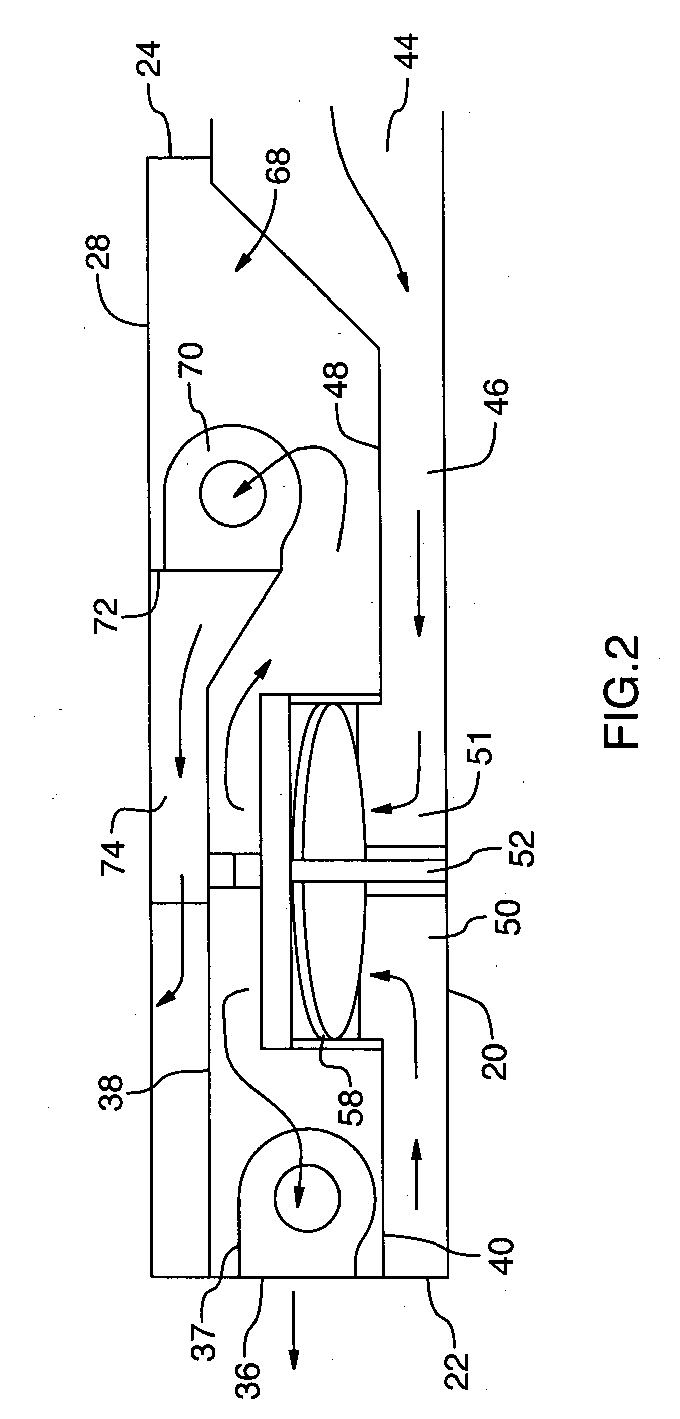
[0010]FIG. 2 is a front elevation of the energy recovery unit of FIG. 1.

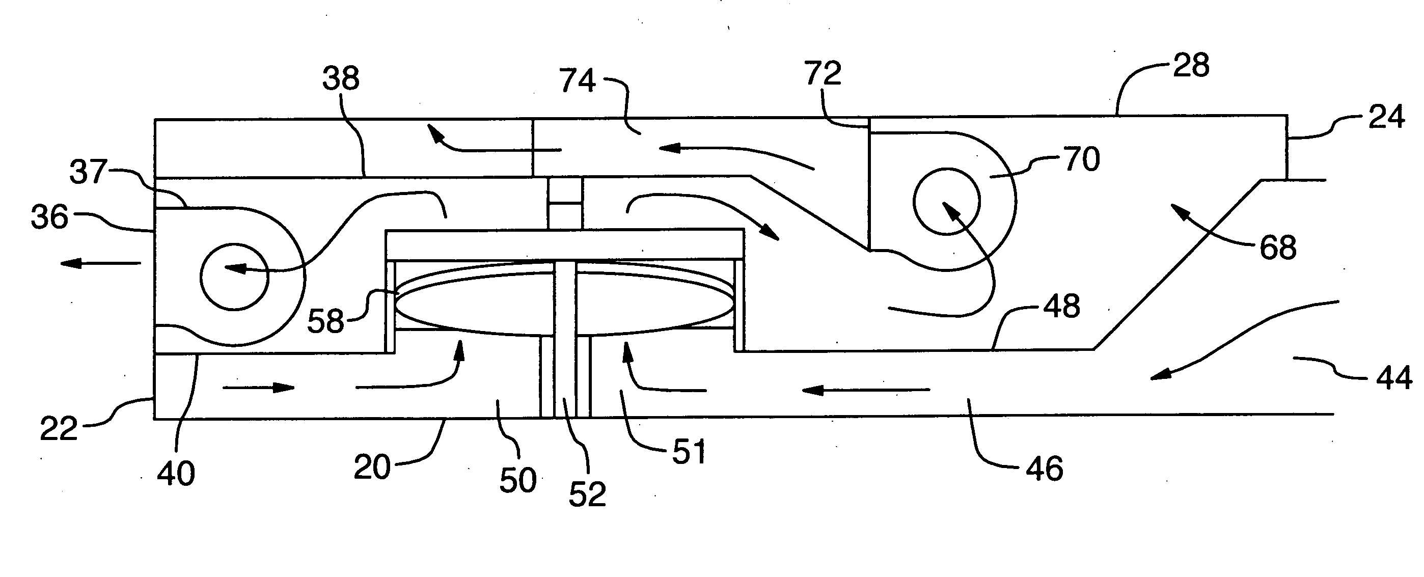
[0011]FIG. 3 is a view on the line III-III of FIG. 2.

[0012] Referring therefore to FIG. 1, an energy recovery unit 10 is located adjacent to a return duct 12 of an air circulation system. The air circulation system includes a supply duct 14 and the ducts 12, 14 are connected through an air handling unit (not shown) that heats or cools the air in the ducts 12, 14.

[0013] The energy recovery unit 10 has an inlet 16 and an outlet 18 that are connected at spaced locations to the return duct 12. As will be described more fully below, a portion of the air in the return duct 12 is diverted through the inlet 16 and a corresponding mass flow of makeup air supplied to the return duct 12 through the outlet 18.

[0014] The ene...


PUM


Abstract

An energy recovery unit has an energy recovery wheel located in a plenum. Expelled air from the return duct is delivered to the plenum and after passing through the wheel is expelled by an exhaust fan through a side-wall. Makeup air is delivered to the plenum and after passing through the wheel is supplied to the return duct by a fan. The makeup air follows a serpentine path from an intake in a side wall to the return duct.

Description

FIELD OF THE INVENTION [0001] The present invention relates to energy recovery units for use with air handling systems. SUMMARY OF THE INVENTION [0002] It is a common practice to heat and cool premises using air as the heat transfer medium. The air is ducted from an air handling unit that can either supply heat to or extract heat from the air to different outlets within the building. Air is returned from the building through a network of return ducts so that the air is continuously circulated within the building. [0003] In order to maintain air quality at the requisite level, it is usual to reject a portion of the return air and replace it with air from outside the building. This maintains the air quality whilst avoiding continuous reheating of the air within the building. However, the air rejected from the building has been conditioned so it represents a significant energy loss if it is simply expelled. Similarly, the makeup air needs to be heated or cooled to the conditions within...

Claims


Application Information

Patent Timeline
IPC IPC(8): F25D23/00F25D17/06
CPCF24F3/1423F24F2203/1004F24F2203/1008F24F2203/1084F24F2203/1032F24F2203/104F24F2203/1068F24F2203/1012
Inventor LATTANZIO, MAURICE
Owner SPINNAKER INDS
Learn More